Troubleshooting Checklist
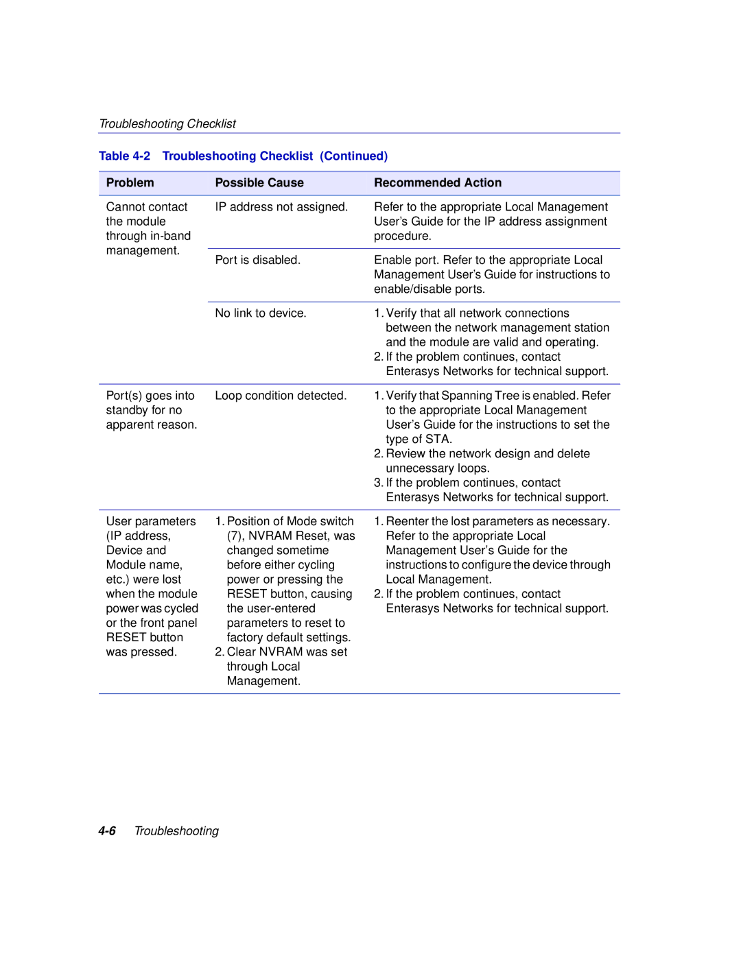
Table 4-2 Troubleshooting Checklist (Continued)
Problem | Possible Cause | Recommended Action | |
|
|
| |
Cannot contact | IP address not assigned. | Refer to the appropriate Local Management | |
the module |
| User’s Guide for the IP address assignment | |
through |
| procedure. | |
management. |
|
| |
Port is disabled. | Enable port. Refer to the appropriate Local | ||
| |||
|
| Management User’s Guide for instructions to | |
|
| enable/disable ports. | |
|
|
| |
| No link to device. | 1. Verify that all network connections | |
|
| between the network management station | |
|
| and the module are valid and operating. | |
|
| 2. If the problem continues, contact | |
|
| Enterasys Networks for technical support. | |
|
|
| |
Port(s) goes into | Loop condition detected. | 1. Verify that Spanning Tree is enabled. Refer | |
standby for no |
| to the appropriate Local Management | |
apparent reason. |
| User’s Guide for the instructions to set the | |
|
| type of STA. | |
|
| 2. Review the network design and delete | |
|
| unnecessary loops. | |
|
| 3. If the problem continues, contact | |
|
| Enterasys Networks for technical support. | |
|
|
| |
User parameters | 1. Position of Mode switch | 1. Reenter the lost parameters as necessary. | |
(IP address, | (7), NVRAM Reset, was | Refer to the appropriate Local | |
Device and | changed sometime | Management User’s Guide for the | |
Module name, | before either cycling | instructions to configure the device through | |
etc.) were lost | power or pressing the | Local Management. | |
when the module | RESET button, causing | 2. If the problem continues, contact | |
power was cycled | the | Enterasys Networks for technical support. | |
or the front panel | parameters to reset to |
| |
RESET button | factory default settings. |
| |
was pressed. | 2. Clear NVRAM was set |
| |
| through Local |
| |
| Management. |
| |
|
|
|