FLASH Upgrade
B.3.2 Installing the FLASH Module
CAUTION: Observe all antistatic precautions when handling sensitive electronic equipment.
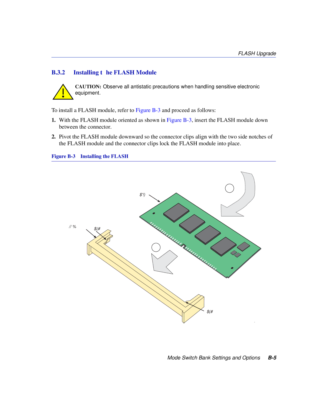
To install a FLASH module, refer to Figure
1.With the FLASH module oriented as shown in Figure
2.Pivot the FLASH module downward so the connector clips align with the two side notches of the FLASH module and the connector clips lock the FLASH module into place.
Figure B-3 Installing the FLASH
2
Flash
Connector Clip
1
![]() Clip
Clip
3387_11
Mode Switch Bank Settings and Options