6H303-48
6H302-48 and 6H303-48 Fast Ethernet User’s Guide
6H302-48
FAST ENET
Page
Enterasys Networks, Inc 35 Industrial Way Rochester, NH
Order Number 9033387-05 October
VCCI NOTICE
FCC NOTICE
INDUSTRY CANADA NOTICE
CLASS A ITE NOTICE
ENTERASYS NETWORKS, INC PROGRAM LICENSE AGREEMENT
BEFORE OPENING OR UTILIZING THE ENCLOSED PRODUCT
CAREFULLY READ THIS LICENSE AGREEMENT
7. NO LIABILITY FOR CONSEQUENTIAL DAMAGES. IN NO EVENT SHALL ENTERASYS OR ITS SUPPLIERS BE LIABLE FOR ANY DAMAGES WHATSOEVER INCLUDING, WITHOUT LIMITATION, DAMAGES FOR LOSS OF BUSINESS, PROFITS, BUSINESS INTERRUPTION, LOSS OF BUSINESS INFORMATION, SPECIAL, INCIDENTAL, CONSEQUENTIAL, OR RELIANCE DAMAGES, OR OTHER LOSS ARISING OUT OF THE USE OR INABILITY TO USE THIS ENTERASYS PRODUCT, EVEN IF ENTERASYS HAS BEEN ADVISED OF THE POSSIBILITY OF SUCH DAMAGES. BECAUSE SOME STATES DO NOT ALLOW THE EXCLUSION OR LIMITATION OF LIABILITY FOR CONSEQUENTIAL OR INCIDENTAL DAMAGES, OR IN THE DURATION OR LIMITATION OF IMPLIED WARRANTIES IN SOME INSTANCES, THE ABOVE LIMITATION AND EXCLUSIONS MAY NOT APPLY TO YOU
DECLARATION OF CONFORMITY
Page
Contents
ABOUT THIS GUIDE
Contents
INDEX
viii Contents
Figures
Figures
Tables
x Tables
USING THIS GUIDE
About This Guide
Important Notices
Matrix E7 Overview and Setup Guide
STRUCTURE OF THIS GUIDE
RELATED DOCUMENTS
6C105 SmartSwitch 6000 Overview and Setup Guide
Document Conventions
DOCUMENT CONVENTIONS
The guide uses the following conventions
About This Guide
GETTING HELP
Introduction
Important Notice
1-2 Introduction
Group Select Switch Port Status LEDs Group Select LEDs Network Ports
Figure 1-1 6H302-48 and 6H303-48 Modules
Network Ports
1.3 HALF-DUPLEX/FULL-DUPLEX AUTO-NEGOTIATION
1.1 CONNECTIVITY
1.2 RUNTIME IP ADDRESS DISCOVERY
1.4 SMARTTRUNK
1.7 PORT/VLAN REDIRECT FUNCTIONS
1.5 REMOTE MONITORING RMON
1.6 BROADCAST SUPPRESSION
Remote Monitoring RMON
1.8 TRAFFIC RATE LIMITING
1.9 FLOW CONTROL
1.11 802.1 PORT PRIORITY
1.10 GARP SWITCH OPERATION
Installation in the Matrix E7 6C107 Chassis
1.12 DISTRIBUTED CHASSIS MANAGEMENT
1.14 SWITCHING OPTIONS
Installation in the SmartSwitch 6000 6C105 Chassis
1.13 MANAGEMENT
Standards Compatibility
1.16 LANVIEW DIAGNOSTIC LEDs
1.15 STANDARDS COMPATIBILITY
1-8 Introduction
2.1 SMARTTRUNK FEATURE
Network Requirements
2.2 10BASE-T NETWORK
2.3 100BASE-TX NETWORK
100BASE-TX Network
2-2 Network Requirements
Installation
3.2 INSTALLING OPTIONAL FLASH UPGRADE
3.3 INSTALLING THE MODULE INTO THE MATRIX E7 CHASSIS
3.1 UNPACKING THE MODULE
To install a module, refer to Figure 3-1 and proceed as follows
3-4 Installation
Installing the Module into the Matrix E7 Chassis
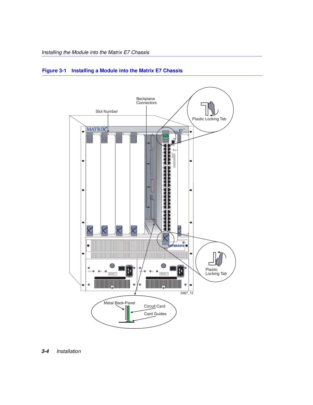
Figure 3-1 Installing a Module into the Matrix E7 Chassis
Backplane Connectors Slot Number
3.4 INSTALLING THE MODULE INTO THE 6C105 CHASSIS
3-6 Installation
Installing the Module into the 6C105 Chassis
Figure 3-2 Installing a Module into the 6C105 Chassis
338702
3.5 CONNECTING TO THE NETWORK
3.5.1 Connecting UTP Cables to the 6H302-48
Figure 3-3 Connecting a Twisted Pair Segment to the 6H302-48
Group Select
Button
3.5.2 Connecting UTP Cables to the 6H303-48
Figure 3-4 Crossover Cable RJ45 Pinouts
Figure 3-5 Straight-Through Cable RJ45 Pinouts
Screw Hole
Figure 3-6 Connecting a Twisted Pair Segment to the 6H303-48
Screw
ScrewScrew Hole
3.6 COMPLETING THE INSTALLATION
Completing the Installation
Installation
Page
Troubleshooting
4.1 USING LANVIEW
Viewing Receive and Transmit Activity
Using LANVIEW
4-2 Troubleshooting
Figure 4-1 LANVIEW LEDs both modules
Ensure chassis has adequate power
Using LANVIEW
Power off
Solid. Resetting, normal
Table 4-1 LANVIEW LEDs Continued
Using LANVIEW
4-4 Troubleshooting
Color State
Table 4-2 Troubleshooting Checklist
4.2 TROUBLESHOOTING CHECKLIST
Troubleshooting Checklist
Problem
Problem
Troubleshooting Checklist
Table 4-2 Troubleshooting Checklist Continued
4-6 Troubleshooting
4.3 USING THE RESET BUTTON
Figure 4-2 RESET Button both modules
Page
Processors/Memory
Specifications
A.1 6H302-48 / 6H303-48 SPECIFICATIONS
Physical Properties
6H302-48
Environmental Requirements
Input/Output Ports
6H303-48
Table A-2 COM Port Pin Assignments
A.2 COM PORT PINOUT ASSIGNMENTS
A.3 REGULATORY COMPLIANCE
Table A-3 Compliance Standards
Page
Mode Switch Bank Settings and Options
B.1 REQUIRED TOOLS
B.2 SETTING THE MODE SWITCHES
DO NOT attempt a Forced BootP unless a BootP server has been configured for the module. The BootP server references the location of a station acting as a Trivial File Transfer Protocol TFTP server containing the module image file
B.3 FLASH UPGRADE
B.3.1 Locating the FLASH Module
B.3.2 Installing the FLASH Module
Page
Index
Numerics
Index-2