Connecting to the Network
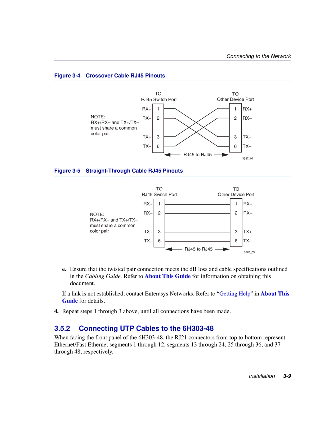
Figure 3-4 Crossover Cable RJ45 Pinouts
NOTE:
RX+/RX– and TX+/TX– must share a common color pair.
| TO |
|
|
|
| TO |
| |||
RJ45 Switch Port |
|
| Other Device Port | |||||||
|
|
|
|
|
|
|
|
|
| RX+ |
RX+ | 1 |
|
|
|
|
|
|
| 1 | |
RX– | 2 |
|
|
|
|
|
|
| 2 | RX– |
TX+ | 3 |
|
|
|
|
|
|
| 3 | TX+ |
|
|
|
|
|
|
| ||||
|
|
|
|
|
|
| ||||
TX– | 6 |
|
|
|
|
|
|
| 6 | TX– |
|
|
|
|
| RJ45 to RJ45 |
|
|
| 3387_04 | |
|
|
|
|
|
| |||||
|
|
|
|
|
|
| ||||
|
|
|
|
|
|
|
|
|
| |
Figure 3-5 Straight-Through Cable RJ45 Pinouts
NOTE:
RX+/RX– and TX+/TX– must share a common color pair.
| TO |
|
|
| TO |
| ||
RJ45 Switch Port |
| Other Device Port | ||||||
|
|
|
|
|
|
|
| RX+ |
RX+ | 1 |
|
|
|
|
| 1 | |
|
|
|
|
| ||||
RX– | 2 |
|
|
|
|
| 2 | RX– |
|
|
|
|
| ||||
TX+ | 3 |
|
|
|
|
| 3 | TX+ |
|
|
|
|
| ||||
TX– | 6 |
|
|
|
|
| 6 | TX– |
|
| RJ45 to RJ45 |
|
| ||||
|
|
|
|
|
|
| 3387_05 | |
|
|
|
|
| ||||
|
|
|
|
|
| |||
|
|
|
|
|
|
|
| |
e.Ensure that the twisted pair connection meets the dB loss and cable specifications outlined in the Cabling Guide. Refer to About This Guide for information on obtaining this document.
If a link is not established, contact Enterasys Networks. Refer to “Getting Help” in About This Guide for details.
4.Repeat steps 1 through 3 above, until all connections have been made.
3.5.2Connecting UTP Cables to the 6H303-48
When facing the front panel of the