Setting the Mode Switches
B.2 SETTING THE MODE SWITCHES
CAUTION: Read the appropriate sections to be fully aware of the consequences when changing switch settings.
Only qualified personnel should change switch settings.
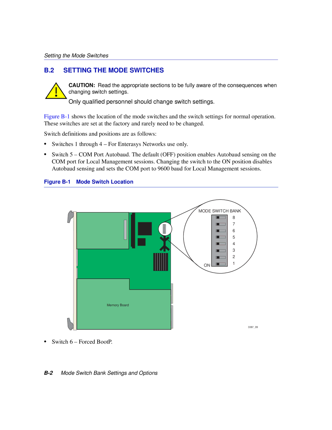
Figure B-1 shows the location of the mode switches and the switch settings for normal operation. These switches are set at the factory and rarely need to be changed.
Switch definitions and positions are as follows:
•Switches 1 through 4 – For Enterasys Networks use only.
•Switch 5 – COM Port Autobaud. The default (OFF) position enables Autobaud sensing on the COM port for Local Management sessions. Changing the switch to the ON position disables Autobaud sensing and sets the COM port to 9600 baud for Local Management sessions.
Figure B-1 Mode Switch Location
MODE SWITCH BANK
ON
8
7
6
5
4
3
2
1
Memory Board
3387_09
•Switch 6 – Forced BootP.
