Connecting to the Network
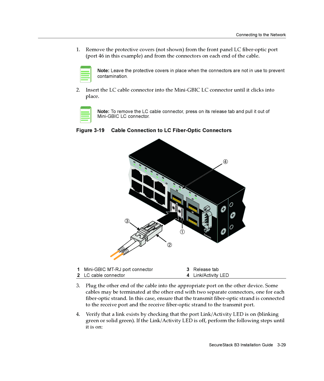
1.Remove the protective covers (not shown) from the front panel LC fiber‐optic port (port 46 in this example) and from the connectors on each end of the cable.
Note: Leave the protective covers in place when the connectors are not in use to prevent contamination.
2.Insert the LC cable connector into the Mini‐GBIC LC connector until it clicks into place.
Note: To remove the LC cable connector, press on its release tab and pull it out of
Figure 3-19 Cable Connection to LC Fiber-Optic Connectors
1 | 3 | Release tab | |
2 | LC cable connector | 4 | Link/Activity LED |
3.Plug the other end of the cable into the appropriate port on the other device. Some cables may be terminated at the other end with two separate connectors, one for each fiber‐optic strand. In this case, ensure that the transmit fiber‐optic strand is connected to the receive port and the receive fiber‐optic strand to the transmit port.
4.Verify that a link exists by checking that the port Link/Activity LED is on (blinking green or solid green). If the Link/Activity LED is off, perform the following steps until it is on:
SecureStack B3 Installation Guide