Connecting to the Network
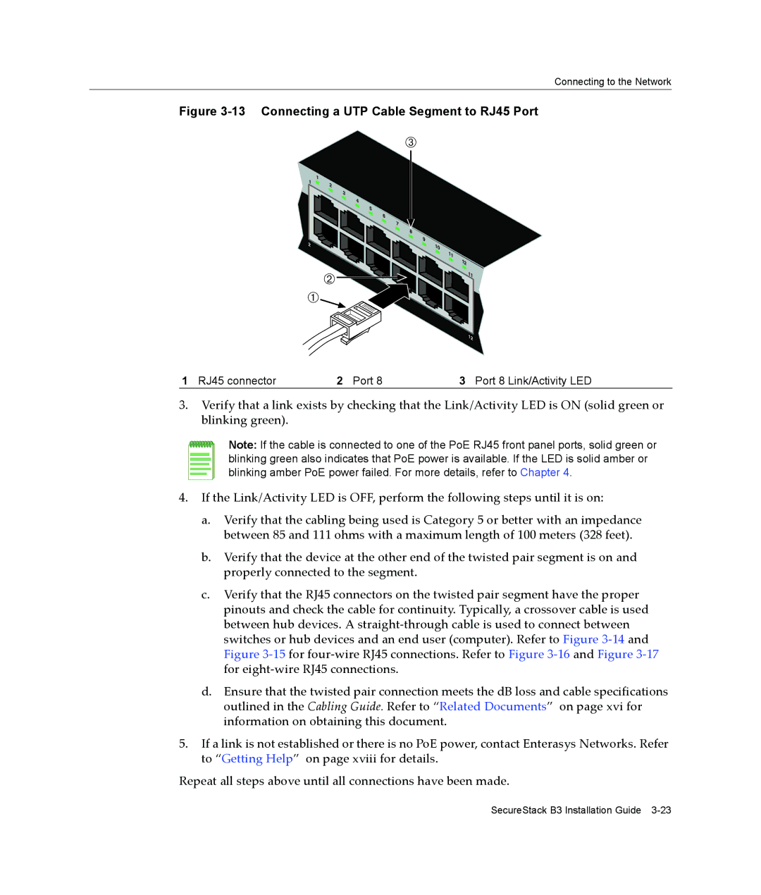
Figure 3-13 Connecting a UTP Cable Segment to RJ45 Port
Â
1 | 1 | |
2 | ||
| ||
| 3 | |
| 4 | |
| 5 | |
| 6 | |
| 7 | |
| 8 | |
2 | 9 | |
10 | ||
|
11
Á
À
12 11
|
| 12 |
1 RJ45 connector | 2 Port 8 | 3 Port 8 Link/Activity LED |
3.Verify that a link exists by checking that the Link/Activity LED is ON (solid green or blinking green).
Note: If the cable is connected to one of the PoE RJ45 front panel ports, solid green or blinking green also indicates that PoE power is available. If the LED is solid amber or blinking amber PoE power failed. For more details, refer to Chapter 4.
4.If the Link/Activity LED is OFF, perform the following steps until it is on:
a.Verify that the cabling being used is Category 5 or better with an impedance between 85 and 111 ohms with a maximum length of 100 meters (328 feet).
b.Verify that the device at the other end of the twisted pair segment is on and properly connected to the segment.
c.Verify that the RJ45 connectors on the twisted pair segment have the proper pinouts and check the cable for continuity. Typically, a crossover cable is used between hub devices. A straight‐through cable is used to connect between switches or hub devices and an end user (computer). Refer to Figure 3‐14 and Figure 3‐15 for four‐wire RJ45 connections. Refer to Figure 3‐16 and Figure 3‐17 for eight‐wire RJ45 connections.
d.Ensure that the twisted pair connection meets the dB loss and cable specifications outlined in the Cabling Guide. Refer to “Related Documents” on page xvi for information on obtaining this document.
5.If a link is not established or there is no PoE power, contact Enterasys Networks. Refer to “Getting Help” on page xviii for details.
Repeat all steps above until all connections have been made.
SecureStack B3 Installation Guide