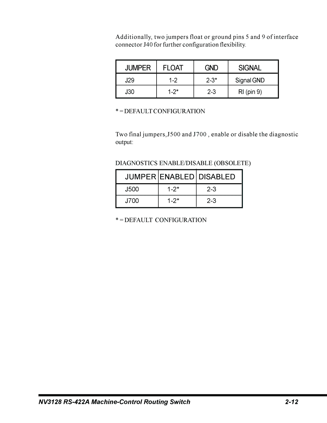
Additionally, two jumpers float or ground pins 5 and 9 of interface connector J40 for further configuration flexibility.
JUMPER | FLOAT | GND | SIGNAL |
J29 | Signal GND | ||
|
|
|
|
J30 | RI (pin 9) | ||
|
|
|
|
* = DEFAULT CONFIGURATION
Two final jumpers,J500 and J700 , enable or disable the diagnostic output:
DIAGNOSTICS ENABLE/DISABLE (OBSOLETE)
JUMPER | ENABLED | DISABLED |
|
|
|
J500 | ||
|
|
|
J700 | ||
|
|
|
* = DEFAULT CONFIGURATION
NV3128 |
