EPSON Perfection 610 | Revision B |
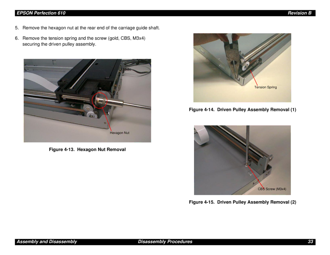
5.Remove the hexagon nut at the rear end of the carriage guide shaft.
6.Remove the tension spring and the screw (gold, CBS, M3x4) securing the driven pulley assembly.
Tension Spring
Figure 4-14. Driven Pulley Assembly Removal (1)
Hexagon Nut
Figure 4-13. Hexagon Nut Removal
CBS Screw (M3x4)
Figure 4-15. Driven Pulley Assembly Removal (2)
Assembly and Disassembly | Disassembly Procedures | 33 |
