| INSTALLATION |
6. GTI TELEPHONE INTERFACE
The 6th step to install the ELI option is to configure each GTI telephone interface to match the type of telephone circuit to be connected to it. The first Main boards, identified by the manufacturer’s number
NOTE
Revision A Main boards do not support Direct Inward Dial (DID) telephone lines. If you need to have a DID telephone line connected to a GTI unit, that GTI unit must contain a
Be careful of terms when talking or reading about the telephone circuit that the GTI unit is to interface. Terms such as send, receive, in, out,
∙
∙
∙
∙
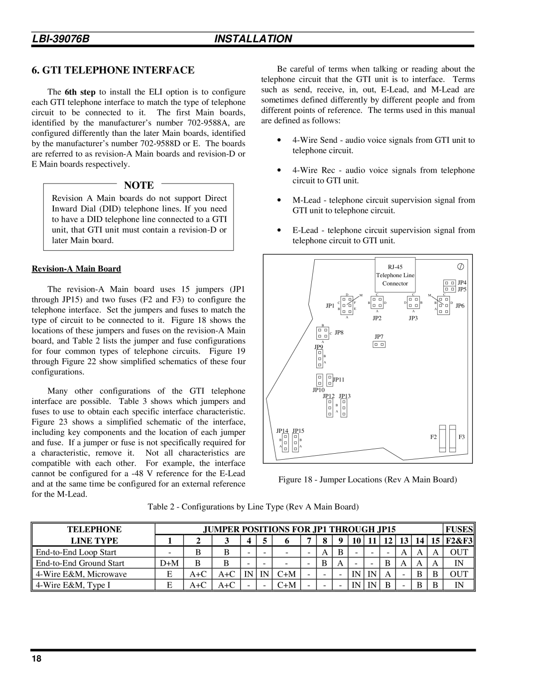
Revision-A Main Board
The
Many other configurations of the GTI telephone interface are possible. Table 3 shows which jumpers and fuses to use to obtain each specific interface characteristic. Figure 23 shows a simplified schematic of the interface, including key components and the location of each jumper and fuse. If a jumper or fuse is not specifically required for a characteristic, remove it. Not all characteristics are compatible with each other. For example, the interface cannot be configured for a
|
|
|
|
|
|
|
|
|
| |
|
|
|
|
| Telephone Line |
|
|
| ||
|
|
|
|
| Connector |
|
|
| JP4 | |
|
| D |
|
| C |
| C |
| C | JP5 |
|
|
| M |
| M |
| ||||
| JP1 | C | F | B | D | D | B | B | D | JP6 |
| B | E |
| A |
| A | A |
| ||
|
|
|
|
|
|
|
|
| ||
|
| A |
|
| JP2 |
| JP3 |
|
|
|
|
|
|
|
|
|
|
|
| ||
| B |
|
|
|
|
|
|
|
|
|
| C | JP8 |
|
| JP7 |
|
|
|
|
|
| A |
|
|
|
|
|
|
|
| |
|
|
|
|
|
|
|
|
|
| |
| JP9 |
|
|
|
|
|
|
|
|
|
| B |
|
|
|
|
|
|
|
|
|
| A |
|
|
|
|
|
|
|
|
|
| JP11 |
|
|
|
|
|
|
|
| |
| JP10 |
|
|
|
|
|
|
|
|
|
| JP12 | JP13 |
|
|
|
|
|
|
|
|
|
| B |
|
|
|
|
|
|
|
|
|
| A |
|
|
|
|
|
|
|
|
JP14 | JP15 |
|
|
|
|
|
| F2 |
| F3 |
B | B |
|
|
|
|
|
|
| ||
|
|
|
|
|
|
|
|
| ||
A | A |
|
|
|
|
|
|
|
|
|
Figure 18 - Jumper Locations (Rev A Main Board)
Table 2 - Configurations by Line Type (Rev A Main Board)
TELEPHONE |
| JUMPER POSITIONS FOR JP1 THROUGH JP15 |
|
|
| FUSES | ||||||||||||
LINE TYPE | 1 | 2 | 3 | 4 | 5 | 6 | 7 | 8 | 9 | 10 | 11 | 12 | 13 | 14 | 15 | F2&F3 | ||
- | B | B | - | - | - | - |
| A | B | - | - | - | A | A | A | OUT | ||
D+M | B | B | - | - | - | - |
| B | A | - | - | B | A | A | A | IN | ||
E | A+C | A+C | IN | IN |
| C+M | - | - | - | IN | IN | A | - | B | B | OUT | ||
E | A+C | A+C | - | - |
| C+M | - | - | - | IN | IN | B | - | B | B | IN | ||
|
|
|
|
|
|
|
|
|
|
|
|
|
|
|
|
|
|
|
18