| INSTALLATION |
be selected using DIP switch sections 2 through 4. The serial printer port can be turned off and on using DIP switch section 5. The proper handshaking protocol for your printer can be selected using DIP switch section 6. The IAM can use both hardware and software handshaking, or just software handshaking. The standard ELI option does not provide a cable for this connection, but
PRINTER
1 | 2 | 3 | 4 | 5 |
6 | 7 | 8 |
| 9 |
Pin |
| Function |
|
|
1 | DTR (Output) |
|
| |
2 |
| NC |
|
|
3 | Tx Data (Output) |
| ||
4 | Rx Data (Input) |
| ||
5 |
| Ground |
|
|
6 |
| NC |
|
|
7 | CTS (Input) |
|
| |
8 |
| NC |
|
|
9 |
| Ground |
|
|
Figure 39 - IAM Printer RS-232 Port
Connecting a serial printer can sometimes entail some trial and error to get things set up properly. If you need to change any of the DIP switch settings, be sure to do a soft reset on the IAM (the IAM will only look at the DIP switch settings as part of the reset sequence).
A soft reset is accomplished by pushing the RESET button on the front panel two times. If the time between the two pushes is too short or too long, the reset will be aborted. The two pushes should be about 1/2 second apart. When the two pushes of the Reset button are spaced correctly, the front panel LEDs will all flash simultaneously as the IAM resets.
13. IAM DIP SWITCH SETTINGS
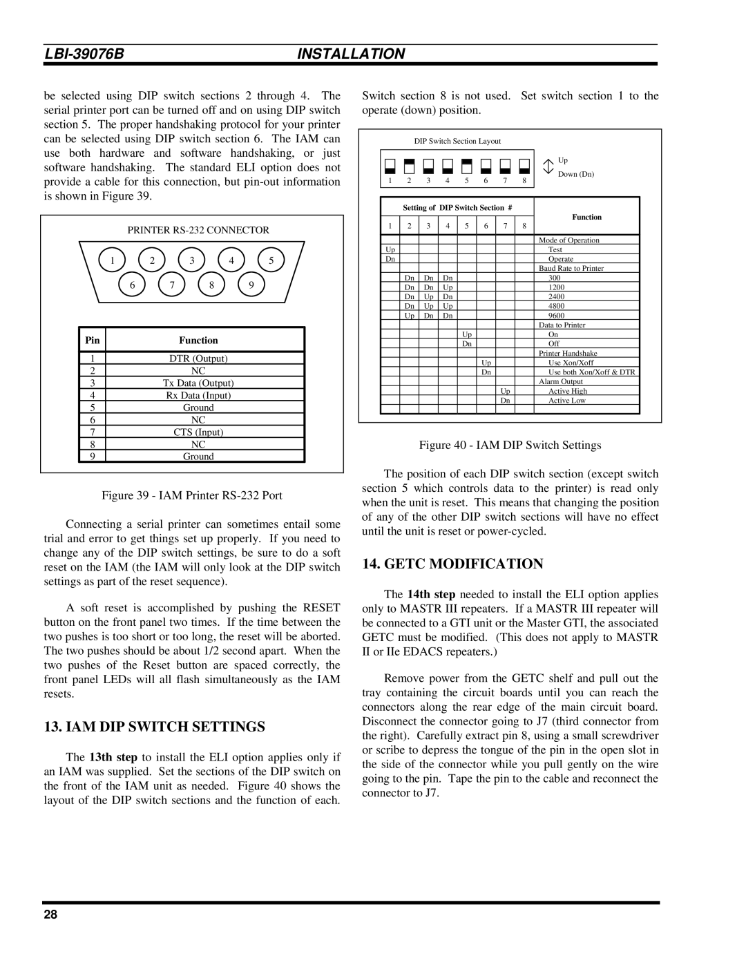
The 13th step to install the ELI option applies only if an IAM was supplied. Set the sections of the DIP switch on the front of the IAM unit as needed. Figure 40 shows the layout of the DIP switch sections and the function of each.
Switch section 8 is not used. Set switch section 1 to the operate (down) position.
|
| DIP Switch Section Layout |
|
| |||
|
|
|
|
|
|
| Up |
1 | 2 | 3 | 4 | 5 | 6 | 7 | Down (Dn) |
8 | |||||||
| Setting of DIP Switch Section # |
|
| ||||||
|
|
|
|
|
|
|
| Function | |
1 | 2 | 3 | 4 | 5 | 6 | 7 | 8 | ||
| |||||||||
|
|
|
|
|
|
|
|
| |
|
|
|
|
|
|
|
| Mode of Operation | |
Up |
|
|
|
|
|
|
| Test | |
Dn |
|
|
|
|
|
|
| Operate | |
|
|
|
|
|
|
|
| Baud Rate to Printer | |
| Dn | Dn | Dn |
|
|
|
| 300 | |
| Dn | Dn | Up |
|
|
|
| 1200 | |
| Dn | Up | Dn |
|
|
|
| 2400 | |
| Dn | Up | Up |
|
|
|
| 4800 | |
| Up | Dn | Dn |
|
|
|
| 9600 | |
|
|
|
|
|
|
|
| Data to Printer | |
|
|
|
| Up |
|
|
| On | |
|
|
|
| Dn |
|
|
| Off | |
|
|
|
|
|
|
|
| Printer Handshake | |
|
|
|
|
| Up |
|
| Use Xon/Xoff | |
|
|
|
|
| Dn |
|
| Use both Xon/Xoff & DTR | |
|
|
|
|
|
|
|
| Alarm Output | |
|
|
|
|
|
| Up |
| Active High | |
|
|
|
|
|
| Dn |
| Active Low | |
|
|
|
|
|
|
|
|
| |
Figure 40 - IAM DIP Switch Settings
The position of each DIP switch section (except switch section 5 which controls data to the printer) is read only when the unit is reset. This means that changing the position of any of the other DIP switch sections will have no effect until the unit is reset or power-cycled.
14. GETC MODIFICATION
The 14th step needed to install the ELI option applies only to MASTR III repeaters. If a MASTR III repeater will be connected to a GTI unit or the Master GTI, the associated GETC must be modified. (This does not apply to MASTR II or IIe EDACS repeaters.)
Remove power from the GETC shelf and pull out the tray containing the circuit boards until you can reach the connectors along the rear edge of the main circuit board. Disconnect the connector going to J7 (third connector from the right). Carefully extract pin 8, using a small screwdriver or scribe to depress the tongue of the pin in the open slot in the side of the connector while you pull gently on the wire going to the pin. Tape the pin to the cable and reconnect the connector to J7.
28