INSTALLATION |
|
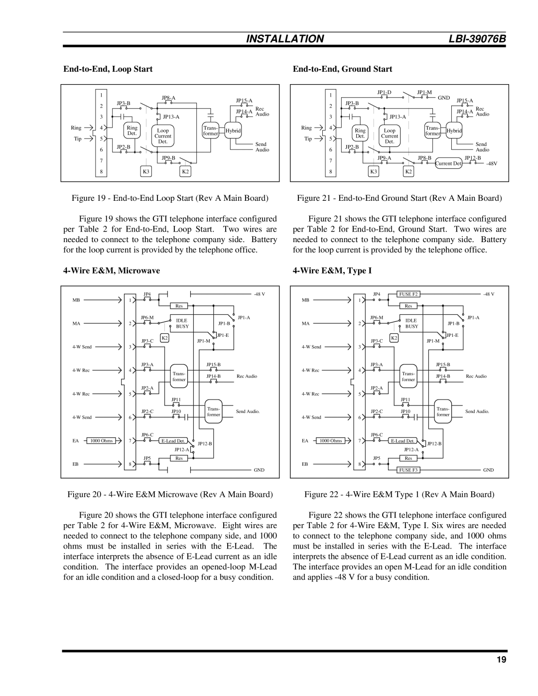
End-to-End, Loop Start
|
|
Ring
Tip
1
2
3![]()
4![]()
5![]()
|
| |||
|
|
| ||
|
|
| Rec | |
|
|
| ||
|
| Audio | ||
|
|
|
| |
Ring | Loop | Trans- | Hybrid |
|
Det. | former |
| ||
Current |
|
| ||
|
|
|
| |
Det. |
|
| Send | |
|
|
| ||
|
|
| Audio | |
|
|
|
| |
|
|
|
| |
| K3 | K2 |
|
|
| 1 |
|
|
| GND |
| ||
|
|
|
|
| ||||
| 2 |
|
|
|
|
| ||
|
|
|
|
|
| Rec | ||
|
|
|
|
|
| |||
|
|
|
|
|
|
| ||
| 3 |
|
|
| Audio | |||
|
|
|
|
|
| |||
Ring | 4 | Ring | Loop | Trans- | Hybrid |
| ||
|
| former |
| |||||
Tip | 5 | Det. | Current |
|
|
| ||
|
|
|
|
| ||||
| Det. |
|
|
|
| Send | ||
|
|
|
|
|
| |||
|
|
|
|
|
|
| ||
| 6 |
|
|
|
|
| Audio | |
|
|
|
|
|
|
| ||
| 7 |
|
|
| ||||
|
|
|
| Current Det. | ||||
|
|
|
|
| ||||
| 8 |
| K3 | K2 |
|
|
|
|
Figure 19 - End-to-End Loop Start (Rev A Main Board)
Figure 21 - End-to-End Ground Start (Rev A Main Board)
Figure 19 shows the GTI telephone interface configured per Table 2 for End-to-End, Loop Start. Two wires are needed to connect to the telephone company side. Battery for the loop current is provided by the telephone office.
Figure 21 shows the GTI telephone interface configured per Table 2 for End-to-End, Ground Start. Two wires are needed to connect to the telephone company side. Battery for the loop current is provided by the telephone office.
|
|
|
| ||
|
| JP4 |
|
| |
MB |
| 1 |
|
|
|
|
|
| Res |
|
|
|
| IDLE |
| ||
MA |
| 2 |
| ||
| BUSY |
| |||
|
|
|
|
| |
|
|
| K2 |
| |
|
|
| |||
|
|
|
| ||
3 |
|
|
| ||
|
|
|
| ||
| 4 | Trans- |
|
| |
|
|
| Rec Audio | ||
|
|
| former | ||
|
|
|
|
| |
|
|
|
|
| |
| 5 |
|
|
| |
|
|
| JP11 |
|
|
|
| JP10 | Trans- | Send Audio. | |
|
| former | |||
6 |
|
| |||
|
|
| |||
|
|
|
|
| |
EA | 1000 Ohms | 7 |
| ||
|
|
|
|
| |
|
|
|
|
| |
|
| JP5 | Res |
|
|
EB |
| 8 |
|
|
|
|
|
|
|
| GND |
Figure 20 - 4-Wire E&M Microwave (Rev A Main Board)
|
|
|
| ||
|
| JP4 | FUSE F2 |
| |
MB |
| 1 |
|
|
|
|
|
| Res |
|
|
|
| IDLE |
| ||
MA |
| 2 |
| ||
| BUSY |
| |||
|
|
|
|
| |
|
|
| K2 |
| |
|
|
| |||
|
|
|
| ||
3 |
|
|
| ||
|
|
|
| ||
| 4 | Trans- |
|
| |
|
|
| Rec Audio | ||
|
|
| former | ||
|
|
|
|
| |
|
|
|
|
| |
| 5 |
|
|
| |
|
|
| JP11 |
|
|
|
| JP10 | Trans- | Send Audio. | |
|
| former | |||
6 |
|
| |||
|
|
| |||
|
|
|
|
| |
EA | 1000 Ohms | 7 |
| ||
|
|
|
|
| |
|
|
|
|
| |
|
| JP5 | Res |
|
|
EB |
| 8 |
|
|
|
|
|
| FUSE F3 |
| GND |
Figure 22 - | |||||
Figure 20 shows the GTI telephone interface configured per Table 2 for 4-Wire E&M, Microwave. Eight wires are needed to connect to the telephone company side, and 1000 ohms must be installed in series with the E-Lead. The interface interprets the absence of E-Lead current as an idle condition. The interface provides an opened-loop M-Lead for an idle condition and a closed-loop for a busy condition.
Figure 22 shows the GTI telephone interface configured per Table 2 for 4-Wire E&M, Type I. Six wires are needed to connect to the telephone company side, and 1000 ohms must be installed in series with the E-Lead. The interface interprets the absence of E-Lead current as an idle condition. The interface provides an open M-Lead for an idle condition and applies -48 V for a busy condition.
19