INSTALLATION |
|
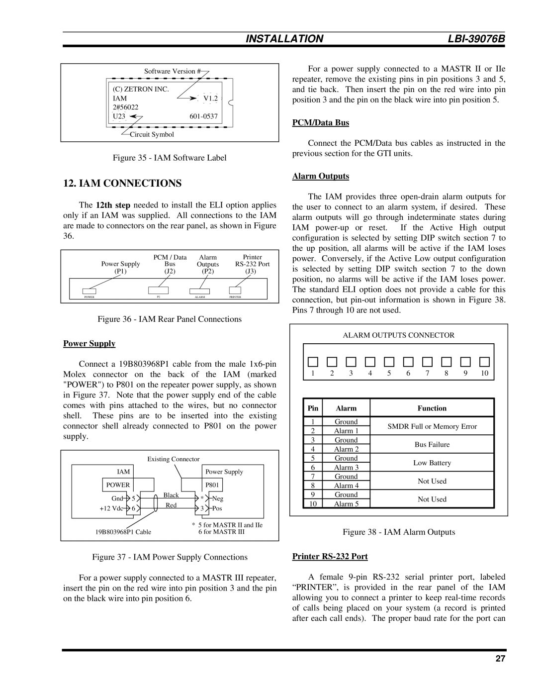
Software Version #
(C) ZETRON INC. |
|
IAM | V1.2 |
2#56022 |
|
U23 |
Circuit Symbol
Figure 35 - IAM Software Label
12. IAM CONNECTIONS
The 12th step needed to install the ELI option applies only if an IAM was supplied. All connections to the IAM are made to connectors on the rear panel, as shown in Figure 36.
|
|
|
| PCM / Data | Alarm |
| Printer | ||
|
|
| Power Supply | Bus | Outputs | ||||
|
|
| (P1) | (J2) | (P2) |
| (J3) | ||
|
|
|
|
|
|
|
|
|
|
|
|
|
|
|
|
|
|
|
|
|
|
|
|
|
|
|
|
|
|
|
| POWER | P2 | ALARM | PRINTER |
| |||
|
|
|
|
|
|
|
|
|
|
Figure 36 - IAM Rear Panel Connections
Power Supply
Connect a 19B803968P1 cable from the male
| Existing Connector |
| |||
IAM |
|
|
| Power Supply | |
POWER |
|
|
| P801 | |
Gnd | 5 | Black | * | Neg | |
Red | |||||
+12 Vdc | 6 | 3 | Pos | ||
| |||||
|
|
| * 5 for MASTR II and IIe | ||
19B803968P1 Cable |
| 6 for MASTR III | |||
Figure 37 - IAM Power Supply Connections
For a power supply connected to a MASTR II or IIe repeater, remove the existing pins in pin positions 3 and 5, and tie back. Then insert the pin on the red wire into pin position 3 and the pin on the black wire into pin position 5.
PCM/Data Bus
Connect the PCM/Data bus cables as instructed in the previous section for the GTI units.
Alarm Outputs
The IAM provides three
ALARM OUTPUTS CONNECTOR
1 | 2 | 3 | 4 | 5 | 6 | 7 | 8 | 9 | 10 | |
|
|
|
|
|
|
|
|
|
| |
|
|
|
|
|
|
|
|
|
| |
Pin |
| Alarm |
|
|
|
| Function |
|
| |
|
|
|
|
|
|
|
|
|
|
|
1 |
| Ground |
|
| SMDR Full or Memory Error |
| ||||
2 |
| Alarm 1 |
|
|
| |||||
|
|
|
|
|
|
|
|
| ||
3 |
| Ground |
|
|
|
| Bus Failure |
|
| |
4 |
| Alarm 2 |
|
|
|
|
|
| ||
|
|
|
|
|
|
|
|
| ||
5 |
| Ground |
|
|
|
| Low Battery |
|
| |
6 |
| Alarm 3 |
|
|
|
|
|
| ||
|
|
|
|
|
|
|
|
| ||
7 |
| Ground |
|
|
|
| Not Used |
|
| |
8 |
| Alarm 4 |
|
|
|
|
|
| ||
|
|
|
|
|
|
|
|
| ||
9 |
| Ground |
|
|
|
| Not Used |
|
| |
10 |
| Alarm 5 |
|
|
|
|
|
| ||
|
|
|
|
|
|
|
|
| ||
Figure 38 - IAM Alarm Outputs
Printer RS-232 Port
For a power supply connected to a MASTR III repeater, insert the pin on the red wire into pin position 3 and the pin on the black wire into pin position 6.
A female
27