| INSTALLATION |
Revision-D or E Main Board
The
Three matrix cards are supplied with each GTI unit. They are labeled
| A1 |
| J5 |
Matrix Board | JP3 |
| A |
| B |
| A |
| B |
| JP4 |
FRONT |
|
Figure 24 - Jumper Locations (Rev D or E Main Board)
Table 4 - Configurations (Rev D or E Main Board)
TELEPHONE | JP3 | JP4 | MATRIX |
LINE TYPE |
|
| CARD |
B | A* | ||
B | A* | ||
A | A* | ||
A | A* | ||
DID | B | A* | DID |
|
|
|
|
*Use the B position when the distance to the PBX is short (gives better hybrid balance).
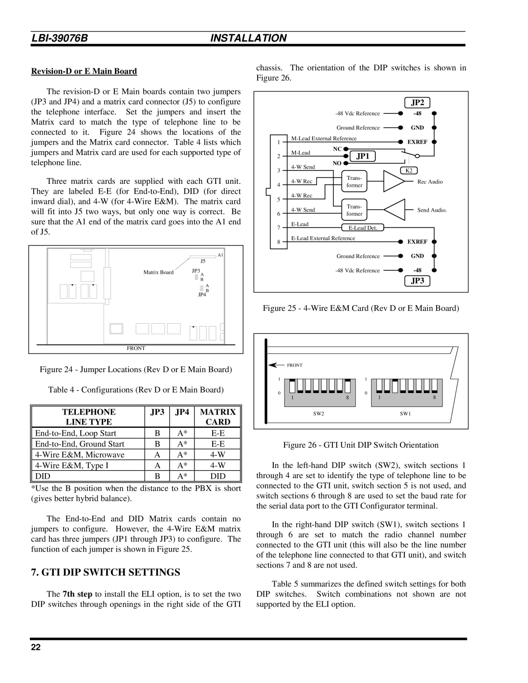
The
7. GTI DIP SWITCH SETTINGS
The 7th step to install the ELI option, is to set the two DIP switches through openings in the right side of the GTI
chassis. The orientation of the DIP switches is shown in Figure 26.
|
|
| JP2 | |
|
| |||
|
| Ground Reference | GND | |
1 | EXREF | |||
|
| |||
| NC |
| ||
2 | JP1 |
| ||
|
| |||
| NO |
| ||
3 |
| K2 | ||
|
| |||
| Trans- | Rec Audio | ||
4 | former | |||
|
| |||
5 |
|
| ||
|
|
| ||
| Trans- | Send Audio. | ||
6 | former | |||
|
| |||
7 |
| |||
|
| |||
8 | EXREF | |||
|
| |||
|
| Ground Reference | GND | |
|
| |||
|
|
| JP3 | |
Figure 25 - 4-Wire E&M Card (Rev D or E Main Board)
FRONT |
|
|
|
1 |
| 1 |
|
0 |
| 0 |
|
1 | 8 | 1 | 8 |
SW2 |
|
| SW1 |
Figure 26 - GTI Unit DIP Switch Orientation
In the left-hand DIP switch (SW2), switch sections 1 through 4 are set to identify the type of telephone line to be connected to the GTI unit, switch section 5 is not used, and switch sections 6 through 8 are used to set the baud rate for the serial data port to the GTI Configurator terminal.
In the right-hand DIP switch (SW1), switch sections 1 through 6 are set to match the radio channel number connected to the GTI unit (this will also be the line number of the telephone line connected to that GTI unit), and switch sections 7 and 8 are not used.
Table 5 summarizes the defined switch settings for both DIP switches. Switch combinations not shown are not supported by the ELI option.
22