3.11 Warning Setup Menu
Diagram 3.19
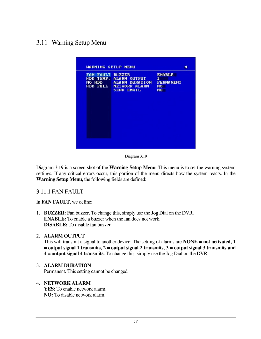
Diagram 3.19 is a screen shot of the Warning Setup Menu. This menu is to set the warning system settings. If any critical errors occur, this portion of the menu directs how the system reacts. In the Warning Setup Menu, the following fields are defined:
3.11.1 FAN FAULT
In FAN FAULT, we define:
1.BUZZER: Fan buzzer. To change this, simply use the Jog Dial on the DVR.
ENABLE: To enable a buzzer when the fan does not work.
DISABLE: To disable fan buzzer.
2.ALARM OUTPUT
This will transmit a signal to another device. The setting of alarms are NONE = not activated, 1 = output signal 1 transmits, 2 = output signal 2 transmits, 3 = output signal 3 transmits and 4 = output signal 4 transmits. To change this, simply use the Jog Dial on the DVR.
3.ALARM DURATION
Permanent. This setting cannot be changed.
4.NETWORK ALARM
YES: To enable network alarm.
NO: To disable network alarm.
57