b)The bend in the drive lever linkages should be positioned downward and slightly outward. If adjustment is needed, loosen jam nut below balljoint and rotate linkage. Tighten jam nut.
Shift transmission lever to fifth gear. Insure that bend in right hand linkage is rotated outward enough that linkage clears shifter lever.
If linkage is rotated too far out, ball joint may bind when drive lever is released into the “drive” position. Insure that this does not happen.
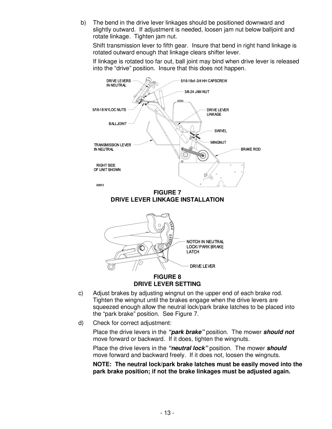
FIGURE 7
DRIVE LEVER LINKAGE INSTALLATION
FIGURE 8
DRIVE LEVER SETTING
c)Adjust brakes by adjusting wingnut on the upper end of each brake rod. Tighten the wingnut until the brakes engage when the drive levers are squeezed enough allow the neutral lock/park brake latches to be placed into the “park brake” position. See Figure 7.
d)Check for correct adjustment:
Place the drive levers in the “park brake” position. The mower should not move forward or backward. If it does, tighten the wingnuts.
Place the drive levers in the “neutral lock” position. The mower should move forward and backward freely. If it does not, loosen the wingnuts.
NOTE: The neutral lock/park brake latches must be easily moved into the park brake position; if not the brake linkages must be adjusted again.
-13 -