3.10Install and adjust shifter lever.
a)Remove the 3/8” nyloc nut and spring disc washer from the stud on top of the transmission. Install the shifter lever through slot in shifter lever plate and onto the stud on top of transmission. Be sure the
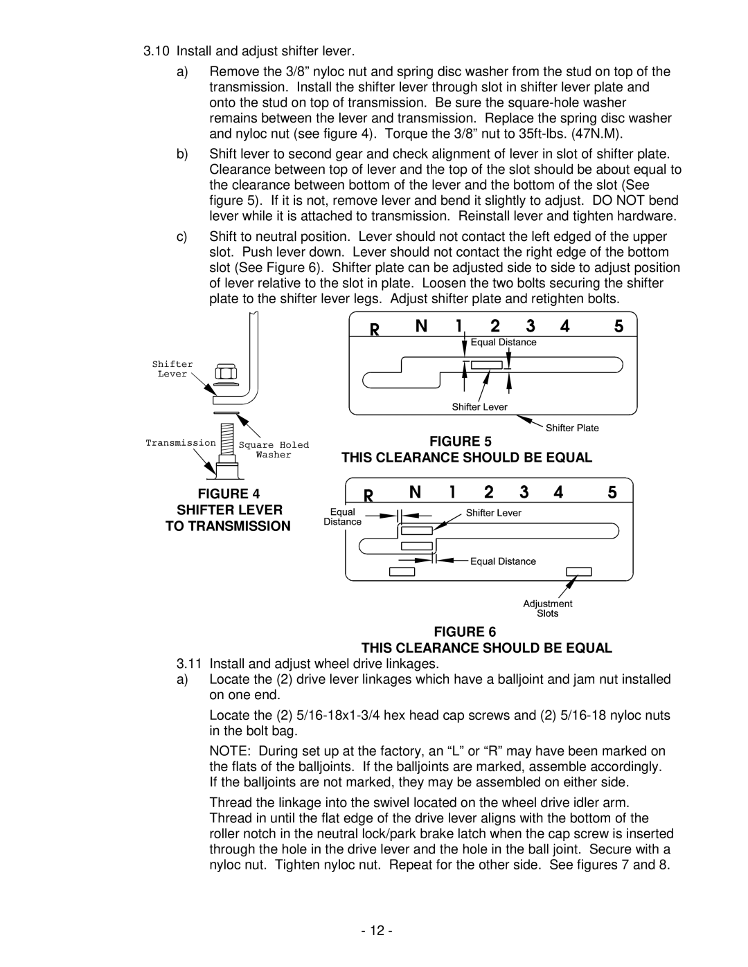
b)Shift lever to second gear and check alignment of lever in slot of shifter plate. Clearance between top of lever and the top of the slot should be about equal to the clearance between bottom of the lever and the bottom of the slot (See figure 5). If it is not, remove lever and bend it slightly to adjust. DO NOT bend lever while it is attached to transmission. Reinstall lever and tighten hardware.
c)Shift to neutral position. Lever should not contact the left edged of the upper slot. Push lever down. Lever should not contact the right edge of the bottom slot (See Figure 6). Shifter plate can be adjusted side to side to adjust position of lever relative to the slot in plate. Loosen the two bolts securing the shifter plate to the shifter lever legs. Adjust shifter plate and retighten bolts.
FIGURE 5
THIS CLEARANCE SHOULD BE EQUAL
FIGURE 4
SHIFTER LEVER
TO TRANSMISSION
FIGURE 6
THIS CLEARANCE SHOULD BE EQUAL
3.11 Install and adjust wheel drive linkages.
a)Locate the (2) drive lever linkages which have a balljoint and jam nut installed on one end.
Locate the (2)
NOTE: During set up at the factory, an “L” or “R” may have been marked on the flats of the balljoints. If the balljoints are marked, assemble accordingly. If the balljoints are not marked, they may be assembled on either side.
Thread the linkage into the swivel located on the wheel drive idler arm. Thread in until the flat edge of the drive lever aligns with the bottom of the roller notch in the neutral lock/park brake latch when the cap screw is inserted through the hole in the drive lever and the hole in the ball joint. Secure with a nyloc nut. Tighten nyloc nut. Repeat for the other side. See figures 7 and 8.
-12 -