MPS 601 specifications
The Extron MPS 601 is a versatile multimedia presentation switcher designed to simplify the management and integration of audio and video signals in various professional environments. This compact equipment caters to classrooms, conference rooms, and other settings that require seamless multimedia presentations.One of the standout features of the MPS 601 is its ability to handle multiple input sources. It offers an array of connectors that include HDMI, VGA, composite video, and audio inputs, allowing users to easily switch between different devices such as laptops, document cameras, and video players. This versatility ensures that presenters can connect their preferred technology without the need for cumbersome adapters or converters.
The MPS 601 incorporates a built-in scaler, which enhances the quality of the output signal by adjusting the resolution to suit the display requirements. This feature ensures optimal image clarity and sharpness, crucial for effective presentations. Additionally, the switcher supports various output resolutions, catering to both standard and high-definition displays.
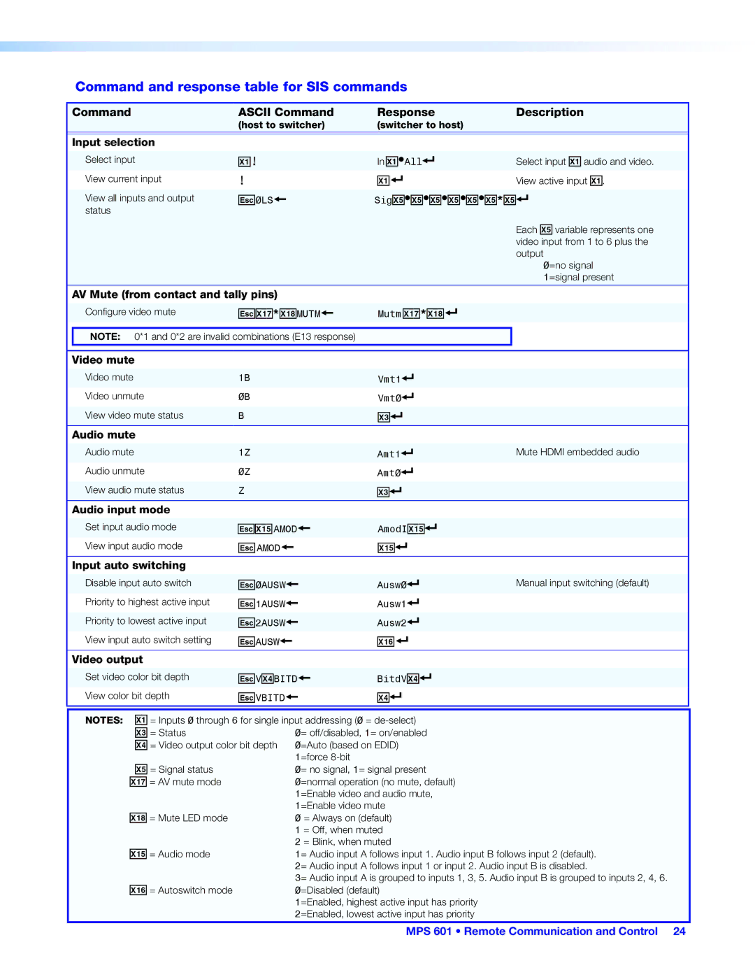
In terms of control options, the MPS 601 provides users with multiple ways to operate the switcher. The front panel features intuitive buttons for quick access to input selection, along with a large, easy-to-read LED display that indicates the currently selected source. Furthermore, users can utilize RS-232 or Ethernet control for integration with third-party control systems, allowing for automation and enhanced functionality.
Another key characteristic of the MPS 601 is its audio capabilities. It supports embedded audio from HDMI sources, as well as separate audio routing through its balanced and unbalanced outputs. This flexibility ensures that audio is perfectly synchronized with video, delivering an immersive multimedia experience.
Furthermore, the MPS 601 is designed with reliability in mind. Extron's commitment to quality ensures that the hardware is built to endure the rigors of daily use, making it a reliable choice for any educational or corporate environment.
In summary, the Extron MPS 601 presents a comprehensive solution for multimedia presentations, combining multiple input handling, advanced scaling capabilities, flexible control options, and robust audio support. This switcher stands out as an essential tool for professionals seeking to enhance their presentation experience while maintaining ease of use and reliability.

