Installation, cont’d
The audio level for each input can be individually set, via the front panel or under
3Digital audio input connections (SW6 YUV A only) — Each input has a female BNC connector for a digital audio input. If you are not switching digital audio, you can use this connector to input the composite sync plane of RGBS video.
Output
4RGB and component video outputs —
RGB models — Connect an RGBHV, RGBS, RGsB, RsGsBs, or component video display or other device to these BNC connectors. Connect the cables as shown in figure
SW6 YUV A — Connect a component video, RGsB, or RsGsBs video display or other device to these BNC connectors. If you are not switching digital audio, you can use the Digital Audio output BNC ( 6 ) to output the sync plane of RGBS video. Connect the cables as shown in figure
CAUTION
The captive screw connector can easily be inadvertently plugged partially into one receptacle and partially into an adjacent receptacle. This misconnection could damage the audio output circuits. Ensure that the captive screw connector is plugged into the desired input or output.
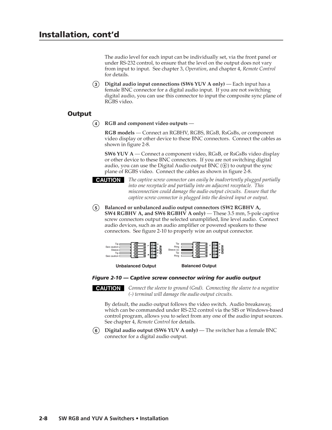
5Balanced or unbalanced audio output connectors (SW2 RGBHV A,
SW4 RGBHV A, and SW6 RGBHV A only) — These 3.5 mm,
Tip
See caution ![]()
Sleeve
Tip
See caution ![]()
Unbalanced Output
Tip
Ring
Sleeve (s)
Tip
Ring
Balanced Output
Figure 2-10 — Captive screw connector wiring for audio output
CAUTION
Connect the sleeve to ground (Gnd). Connecting the sleeve to a negative
By default, the audio output follows the video switch. Audio breakaway, which can be commanded under
6Digital audio output (SW6 YUV A only) — The switcher has a female BNC connector for a digital audio output.