Features
Audio switching models
Inputs — These switchers input 2, 4, or 6 stereo audio signals, balanced or unbalanced, on 3.5 mm,
Outputs — The selected audio input is buffered and output, balanced or unbalanced, on a 3.5 mm,
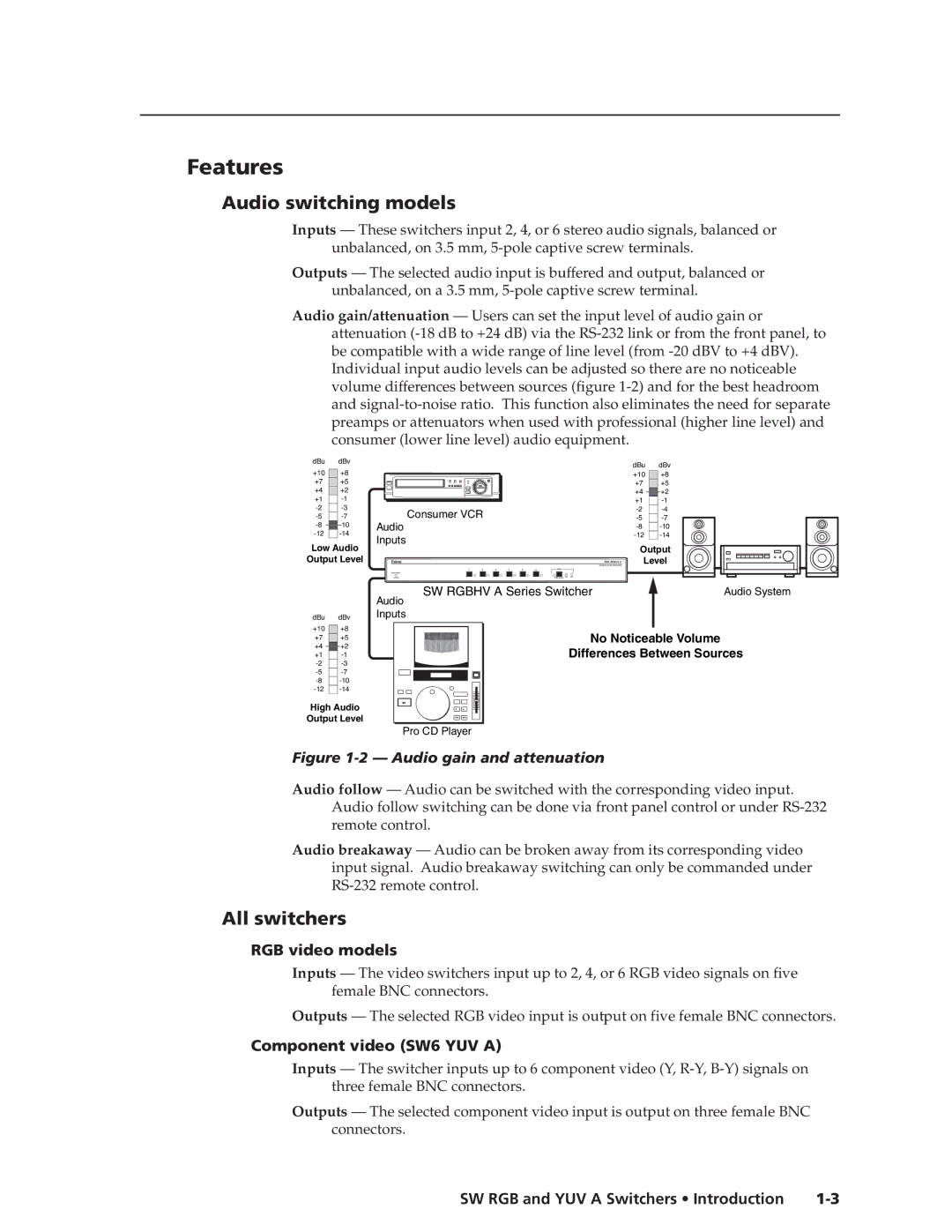
Audio gain/attenuation — Users can set the input level of audio gain or attenuation
dBu | dBv |
|
|
|
|
|
|
|
+10 | +8 |
|
|
|
|
|
|
|
+7 | +5 |
|
|
|
|
|
|
|
+4 | +2 |
|
|
|
|
|
|
|
+1 |
|
|
|
|
|
|
| |
Consumer VCR |
|
|
|
|
| |||
|
|
|
|
| ||||
Audio |
|
|
|
|
|
| ||
|
|
|
|
|
| |||
Inputs |
|
|
|
|
|
| ||
Low Audio |
|
|
|
|
|
| ||
|
|
|
|
|
|
| ||
Output Level |
|
|
|
|
|
| SW6 RGBHV A | |
|
|
|
|
|
|
|
| RGBHV & AUDIO SWITCHER |
|
| 1 | 2 | 3 | 4 | 5 | 6 | AUDIO |
dBu |
| dBv | ||
+10 |
|
| +8 | |
+7 |
|
| +5 | |
+4 |
|
|
| +2 |
+1 |
|
| ||
|
| |||
|
| |||
|
| |||
|
| |||
Output
Level
CONF/SAVE | +dB |
|
| SW RGBHV A Series Switcher | Audio System |
|
| Audio |
|
dBu | dBv | Inputs |
|
+10 | +8 | No Noticeable Volume |
|
+7 | +5 |
| |
+4 | +2 | Differences Between Sources | |
+1 | |||
|
| ||
|
| ||
|
| ||
|
| ||
High Audio |
|
| |
Output Level |
|
| |
|
| Pro CD Player |
|
Figure 1-2 — Audio gain and attenuation
Audio follow — Audio can be switched with the corresponding video input. Audio follow switching can be done via front panel control or under
Audio breakaway — Audio can be broken away from its corresponding video input signal. Audio breakaway switching can only be commanded under
All switchers
RGB video models
Inputs — The video switchers input up to 2, 4, or 6 RGB video signals on five female BNC connectors.
Outputs — The selected RGB video input is output on five female BNC connectors.
Component video (SW6 YUV A)
Inputs — The switcher inputs up to 6 component video (Y,
Outputs — The selected component video input is output on three female BNC connectors.