Installation, cont’d
5. Slide the switcher up and down or back and forth in the mounting brackets until the face of the switcher is at the desired height. Tighten the screws that secure the bracket in place.
If the screws are inaccessible to a screwdriver:
a. | Mark the location of the brackets relative to the screws. |
b. | Remove the switcher from the underside of the surface. |
c. | Tighten the screws. |
d. | Replace the switcher on the underside of the surface (step 4). |
Cabling and Rear Panel Views
| INPUT 1 | |
|
| |
R | G | B |
| INPUT 2 |
8
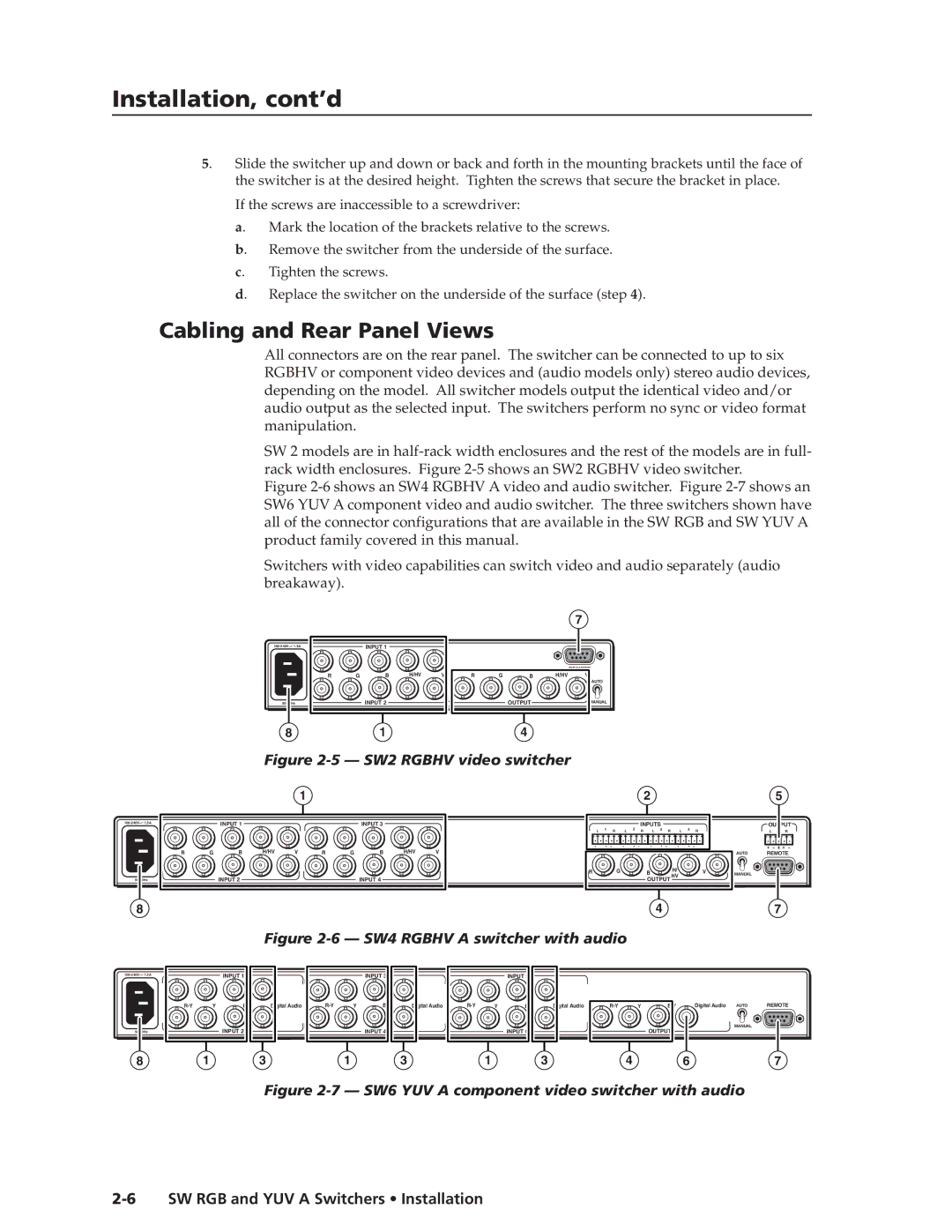
All connectors are on the rear panel. The switcher can be connected to up to six RGBHV or component video devices and (audio models only) stereo audio devices, depending on the model. All switcher models output the identical video and/or audio output as the selected input. The switchers perform no sync or video format manipulation.
SW 2 models are in
Figure 2-6 shows an SW4 RGBHV A video and audio switcher. Figure 2-7 shows an SW6 YUV A component video and audio switcher. The three switchers shown have all of the connector configurations that are available in the SW RGB and SW YUV A product family covered in this manual.
Switchers with video capabilities can switch video and audio separately (audio breakaway).
|
|
| 7 |
|
INPUT 1 |
|
|
| |
| GB H/HV V |
| REMOTE |
|
R | RGB | H/HV V |
| |
|
|
| AUTO |
|
INPUT 2 | OUTPUT | MANUAL |
| |
8 | 1 | 4 |
|
|
Figure |
| |||
1 |
|
| 2 | 5 |
|
|
|
| INPUT 3 |
|
| 1 |
|
| 2 | INPUTS |
|
|
|
|
| OUTPUT | |||
|
|
|
|
|
| L | R | L | R | L | 3 | R | L | 4 | R |
| L | R | ||
H/HV | V | R | G | B | H/HV | V |
|
|
|
|
|
|
|
|
|
|
| AUTO | REMOTE | |
|
|
|
|
|
| R |
|
| G |
|
| B |
| H/ |
|
| V | MANUAL |
|
|
|
|
|
| INPUT 4 |
|
|
|
|
|
|
| OUTPUT HV |
|
|
|
|
|
| ||
47
Figure 2-6 — SW4 RGBHV A switcher with audio
1.3A |
| INPUT 1 |
|
|
| INPUT 3 |
|
|
| INPUT 5 |
|
|
|
|
|
|
| |
|
|
|
|
|
|
|
|
|
|
|
|
|
|
|
| |||
| Y | Digital Audio | Y | Digital Audio | Y | Digital Audio | Y | Digital Audio | AUTO | REMOTE | ||||||||
|
|
| INPUT 2 |
|
|
| INPUT 4 |
|
|
| INPUT 6 |
|
|
| OUTPUT |
| MANUAL |
|
|
|
|
|
|
|
|
|
|
|
|
|
| ||||||
8 |
| 1 |
| 3 |
| 1 |
| 3 |
| 1 |
| 3 |
| 4 |
| 6 |
| 7 |