USP 405 specifications
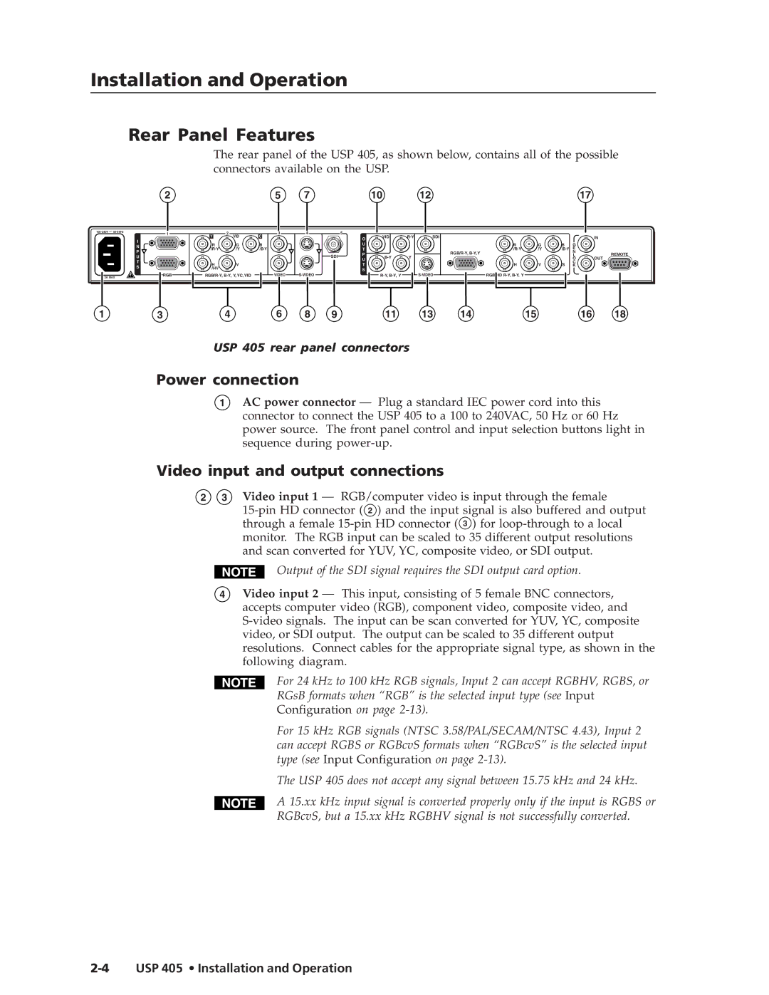
The Extron Electronics USP 405 is a versatile and high-performance solution designed specifically for managing audio and video signals in varied settings, including classrooms, conference rooms, and other collaboration spaces. This compact device excels in providing seamless connectivity, enhanced audio, and video quality, making it an essential component for modern AV system integration.One of the key features of the USP 405 is its ability to support multiple input formats. With a blend of HDMI, DisplayPort, and analog video inputs, it offers unmatched flexibility for connecting various devices such as laptops, tablets, and other multimedia equipment. This ensures users can easily share content without worrying about compatibility issues.
Equipped with advanced signal processing technologies, the USP 405 enhances both video and audio performance. The device includes sophisticated scaling capabilities that automatically adjust the resolution of the video output to match the display device specifications, ensuring optimal viewing experiences. Additionally, the built-in audio embedding and de-embedding features allow for seamless integration of audio sources, enhancing clarity and reducing wiring complexity.
Another standout characteristic of the USP 405 is its intuitive user interface. The front panel features clearly labeled controls for easy operation, while the device can also be controlled via network protocols. This means it can be integrated into existing control systems and managed remotely, streamlining AV operations.
The USP 405 also incorporates Extron's renowned signal integrity technologies, which help maintain high-quality signal transmission over long distances. This ensures that audio and video remain clear and reliable, even in larger setups where cable runs can be extensive.
Durability and reliability are crucial in any AV setup, and the USP 405 is built to withstand the rigors of daily use. Its robust design and fanless architecture reduce potential points of failure while ensuring quiet operation, making it an ideal choice for noise-sensitive environments.
In conclusion, the Extron USP 405 provides a comprehensive suite of features aimed at enhancing AV performance and integration. With its multiple input types, advanced signal processing, user-friendly control options, and durable design, it stands out as a powerful tool for any modern AV installation. Whether in educational settings, corporate environments, or entertainment venues, the USP 405 helps create engaging and productive audiovisual experiences.

