AN50 | APPLICATION NOTE |
|
|
Embedded Sense Resistor (PC Trace Resistor)
Embedded PC trace resistors have the advantage of near zero cost implementation. However, the value of the PC trace resistor has large variations. Embedded resistors have 3 major error sources: the sheet resistivity of the inner layer, the mismatch due to L/W, and the temperature variation of the resistor. All three error sources must be considered for laying out embedded sense resistors.
•Sheet resistivity.
For 1 ounce copper, the thickness variation is typically 1.15 mil to 1.35 mil. Therefore error due to sheet resistiv- ity is (1.35 - 1.15)/1.25 = 16%
•Mismatch due to L/W.
Percent error in L/W is dictated by geometry and the power dissipation capability of the sense resistor. The sense resistor must be able to handle the load current and therefore requires a minimum width which is calculated as follows.
IL
W =
0.05
where: W = minimum width required for proper power dissipation (mils) and IL = Load Current in Amps.
For 15A of load current, minimum width required is 300mils, which reflects a 1% L/W error.
•Thermal Consideration.
Due to I2R power losses the surface temperature of the resistor will increase leading to a higher value. In addition, ambient temperature
variation will add the change in resistor value:
R = R20[1 + α20(T – 20)]
where: R20 is the resistance at 20°C, α20 = 0.00393/ °C, T is the operating temperature, and R is the desired value.
For temperature T = 50°C, the %R change = 12%.
Table 9 is the summary of the tolerance for the Embedded PC Trace Resistor.
Table 9. Summary PC Trace Resistor Tolerance
Tolerance due to Sheet Resistivity variation | 16% |
|
|
Tolerance due to L/W error | 1% |
|
|
Tolerance due to temperature variation | 12% |
|
|
Total Tolerance for PC Trace Resistor | 29% |
|
|
Design Rules for Using an Embedded Resistor The basic equation for laying an embedded resistor is:
R =
ρ × L
W × t
where:
ρ=
L = Length(mils), | L | |
W = Width(mils), and | W | |
| t | |
| ||
t = Thickness(mils). |
| |
|
| |
For 1oz copper, t = 1.35 mils, ρ = 717.86
For example, you can layout a 5.30mΩ embedded sense resistor using the equations above:
| IL |
| 10 |
|
|
W = | = | = 200mils |
| ||
L = | = | = 2000mils | |||
| ρ |
|
| 717.86 |
|
L/W = 10 ■
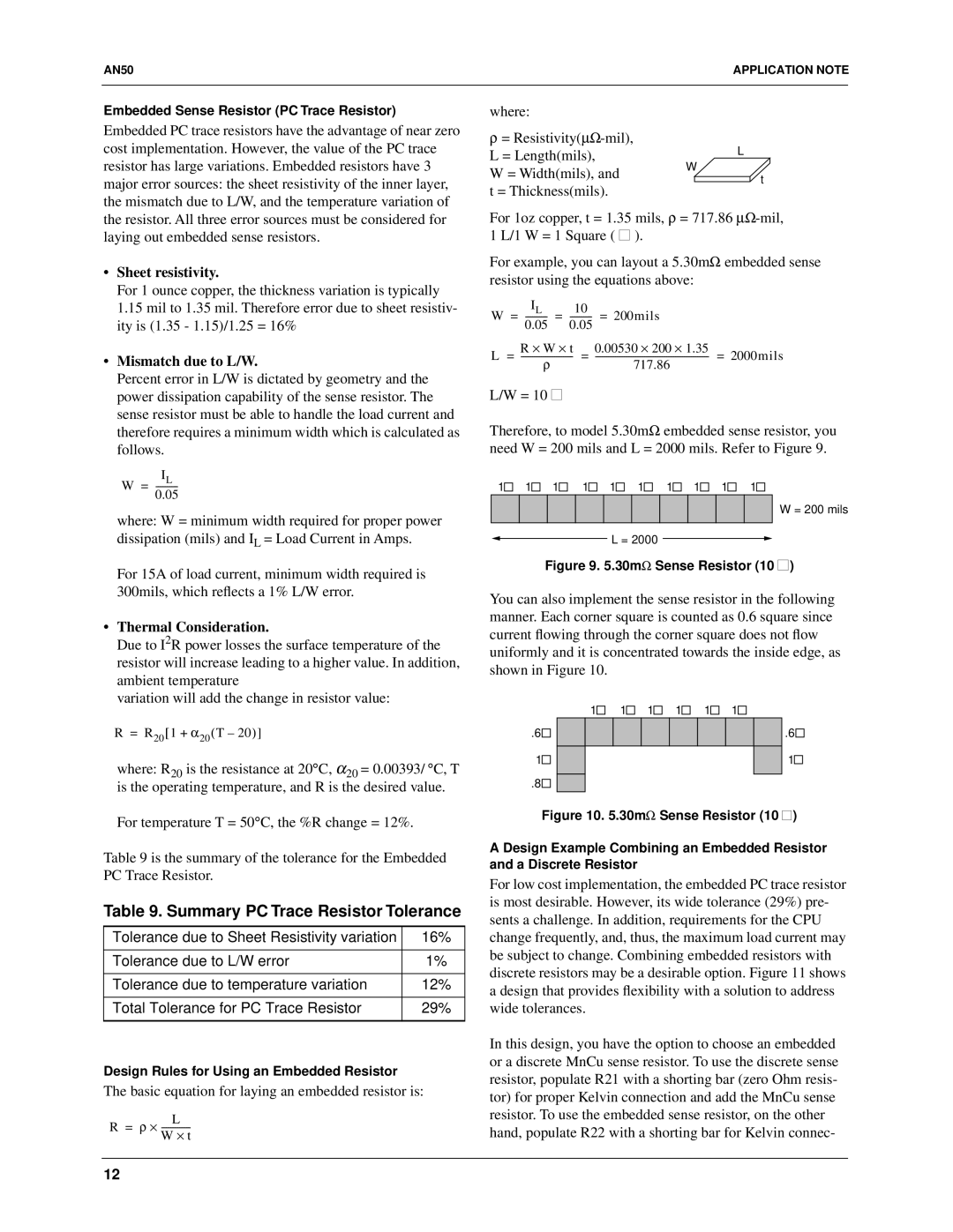
Therefore, to model 5.30mΩ embedded sense resistor, you need W = 200 mils and L = 2000 mils. Refer to Figure 9.
1![]() 1
1![]() 1
1![]() 1
1![]()
![]() 1
1![]()
![]() 1
1![]()
![]() 1
1![]()
![]() 1
1![]()
![]() 1
1![]()
![]() 1
1![]()
![]()
W = 200 mils
L = 2000
Figure 9. 5.30mΩ Sense Resistor (10 ■)
You can also implement the sense resistor in the following manner. Each corner square is counted as 0.6 square since current flowing through the corner square does not flow uniformly and it is concentrated towards the inside edge, as shown in Figure 10.
1 | 1 | 1 | 1 | 1 | 1 |
.6 |
|
|
|
| .6 |
1 |
|
|
|
| 1 |
.8 |
|
|
|
|
|
Figure 10. 5.30mΩ Sense Resistor (10 ■) | |||||
A Design Example Combining an Embedded Resistor and a Discrete Resistor
For low cost implementation, the embedded PC trace resistor is most desirable. However, its wide tolerance (29%) pre- sents a challenge. In addition, requirements for the CPU change frequently, and, thus, the maximum load current may be subject to change. Combining embedded resistors with discrete resistors may be a desirable option. Figure 11 shows a design that provides flexibility with a solution to address wide tolerances.
In this design, you have the option to choose an embedded or a discrete MnCu sense resistor. To use the discrete sense resistor, populate R21 with a shorting bar (zero Ohm resis- tor) for proper Kelvin connection and add the MnCu sense resistor. To use the embedded sense resistor, on the other hand, populate R22 with a shorting bar for Kelvin connec-
12