AN50 | APPLICATION NOTE |
|
|
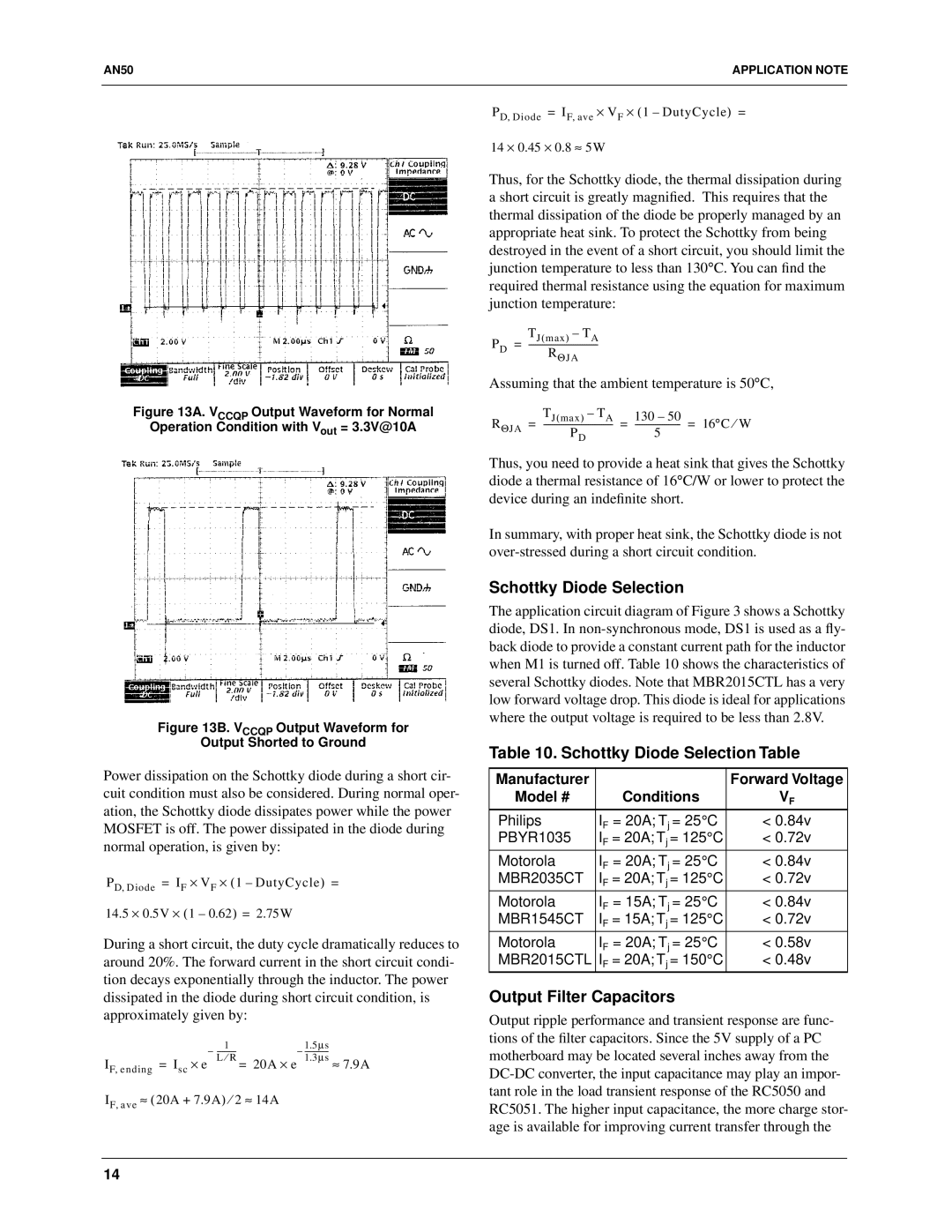
Figure 13A. VCCQP Output Waveform for Normal
Operation Condition with Vout = 3.3V@10A
Figure 13B. VCCQP Output Waveform for
Output Shorted to Ground
Power dissipation on the Schottky diode during a short cir- cuit condition must also be considered. During normal oper- ation, the Schottky diode dissipates power while the power MOSFET is off. The power dissipated in the diode during normal operation, is given by:
PD, Diode = IF × VF × (1 – DutyCycle) =
14.5 × 0.5V × (1 – 0.62) = 2.75W
During a short circuit, the duty cycle dramatically reduces to around 20%. The forward current in the short circuit condi- tion decays exponentially through the inductor. The power dissipated in the diode during short circuit condition, is approximately given by:
– | – | µs- | ||
IF, ending = Isc × e | L ⁄ R = 20A × e |
| 1.3 | µs ≈ 7.9A |
IF, ave ≈ (20A + 7.9A) ⁄ 2 ≈ 14A
PD, Diode = IF, ave × VF × (1 – DutyCycle) =
14 × 0.45 × 0.8 ≈ 5W
Thus, for the Schottky diode, the thermal dissipation during a short circuit is greatly magnified. This requires that the thermal dissipation of the diode be properly managed by an appropriate heat sink. To protect the Schottky from being destroyed in the event of a short circuit, you should limit the junction temperature to less than 130°C. You can find the required thermal resistance using the equation for maximum junction temperature:
PD | TJ(max) – TA |
= | |
| RΘJA |
Assuming that the ambient temperature is 50°C,
RΘJA | TJ(max) – TA | = | 130 – 50 | = 16°C ⁄ W |
= | ||||
| PD |
|
|
Thus, you need to provide a heat sink that gives the Schottky diode a thermal resistance of 16°C/W or lower to protect the device during an indefinite short.
In summary, with proper heat sink, the Schottky diode is not
Schottky Diode Selection
The application circuit diagram of Figure 3 shows a Schottky diode, DS1. In
Table 10. Schottky Diode Selection Table
Manufacturer |
| Forward Voltage |
Model # | Conditions | VF |
Philips | IF = 20A; Tj = 25°C | < 0.84v |
PBYR1035 | IF = 20A; Tj = 125°C | < 0.72v |
Motorola | IF = 20A; Tj = 25°C | < 0.84v |
MBR2035CT | IF = 20A; Tj = 125°C | < 0.72v |
Motorola | IF = 15A; Tj = 25°C | < 0.84v |
MBR1545CT | IF = 15A; Tj = 125°C | < 0.72v |
Motorola | IF = 20A; Tj = 25°C | < 0.58v |
MBR2015CTL | IF = 20A; Tj = 150°C | < 0.48v |
Output Filter Capacitors
Output ripple performance and transient response are func- tions of the filter capacitors. Since the 5V supply of a PC motherboard may be located several inches away from the
14