APPLICATION NOTE | AN50 |
|
|
VID | Iload (A) | Vout (V) |
11010 | 0.5 | 2.505 |
|
|
|
| 1.0 | 2.504 |
|
|
|
| 2.0 | 2.501 |
|
|
|
| 3.0 | 2.496 |
|
|
|
| 4.0 | 2.493 |
|
|
|
| 5.0 | 2.493 |
|
|
|
| 6.0 | 2.492 |
|
|
|
| 7.0 | 2.492 |
|
|
|
| 8.0 | 2.491 |
|
|
|
| 9.0 | 2.490 |
|
|
|
| 10.0 | 2.989 |
|
|
|
| 11.0 | 2.488 |
|
|
|
| 12.0 | 2.486 |
|
|
|
| 13.0 | 2.485 |
|
|
|
| 13.9 | 2.484 |
|
|
|
Load Regulation 0.5A – 13.9A | 0.84% | |
|
|
|
Note:
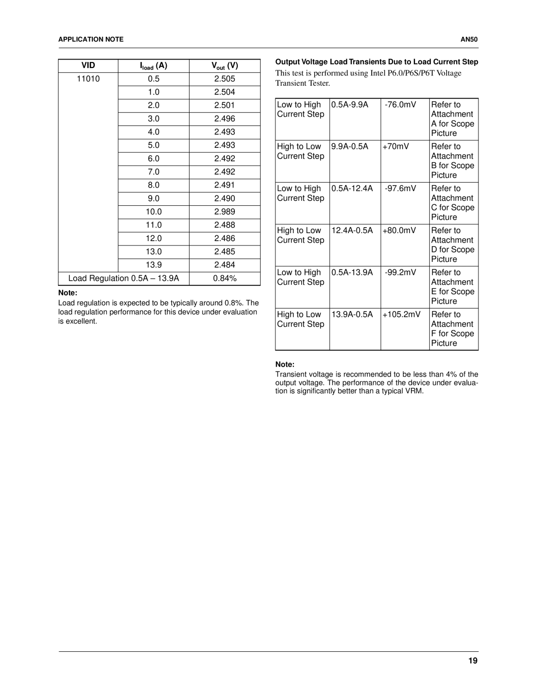
Load regulation is expected to be typically around 0.8%. The load regulation performance for this device under evaluation is excellent.
Output Voltage Load Transients Due to Load Current Step
This test is performed using Intel P6.0/P6S/P6T Voltage Transient Tester.
Low to High | Refer to | ||
Current Step |
|
| Attachment |
|
|
| A for Scope |
|
|
| Picture |
|
|
|
|
High to Low | +70mV | Refer to | |
Current Step |
|
| Attachment |
|
|
| B for Scope |
|
|
| Picture |
|
|
|
|
Low to High | Refer to | ||
Current Step |
|
| Attachment |
|
|
| C for Scope |
|
|
| Picture |
|
|
|
|
High to Low | +80.0mV | Refer to | |
Current Step |
|
| Attachment |
|
|
| D for Scope |
|
|
| Picture |
|
|
|
|
Low to High | Refer to | ||
Current Step |
|
| Attachment |
|
|
| E for Scope |
|
|
| Picture |
|
|
|
|
High to Low | +105.2mV | Refer to | |
Current Step |
|
| Attachment |
|
|
| F for Scope |
|
|
| Picture |
|
|
|
|
Note:
Transient voltage is recommended to be less than 4% of the output voltage. The performance of the device under evalua- tion is significantly better than a typical VRM.
19
