APPLICATION NOTE | AN50 |
|
|
FET. Low Equivalent Series Resistance (ESR) capacitors are best suited for this type of application. Incorrect selection can hinder the converter's overall performance. The input capacitor should be placed as close to the drain of the FET as possible to reduce the effect of ringing caused by long trace lengths.
The ESR rating of a capacitor is a difficult number to quantify. ESR is defined as the resonant impedance of the capacitor. Since the capacitor is actually a complex imped- ance device having resistance, inductance, and capacitance, it is natural for this device to have a resonant frequency. As a rule, the lower the ESR, the better suited the capacitor is for use in switching power supply applications. Many capacitor manufacturers do not supply ESR data. A useful estimate of the ESR can be obtained using the following equation:
DF
ESR =
2πfC
where DF is the dissipation factor of the capacitor, f is the operating frequency, and C is the capacitance in farads.
With this in mind, correct calculation of the output capaci- tance is crucial to the performance of the
C(µF) | IO × ΔT |
= |
where ΔV is the maximum voltage deviation due to load transients, ΔT is the reaction time of the power source (loop response time for the RC5050 and RC5051 isapproximately 2µs), and IO is the output load current.
For IO = 12.2A
C(µF) | IO × ΔT | 12.2A × 2µs | = 2870µF |
= |
Because the control loop response of the controller is not instantaneous, the initial load transient must be supplied entirely by the output capacitors. The initial voltage deviation is determined by the total ESR of the capacitors used and the parasitic resistance of the output traces. For a detailed analysis of capacitor requirements in a
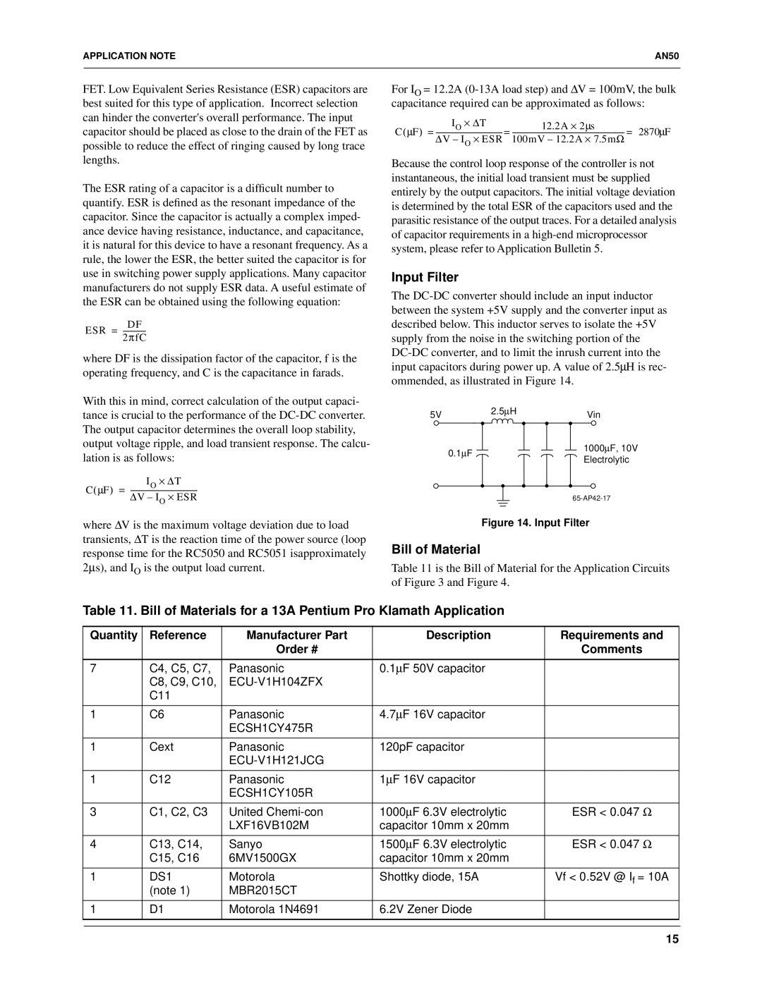
Input Filter
The
5V |
| 2.5∝H | Vin |
|
| ||
| 0.1∝F |
| 1000∝F, 10V |
|
| Electrolytic | |
|
|
| |
|
|
|
Figure 14. Input Filter
Bill of Material
Table 11 is the Bill of Material for the Application Circuits of Figure 3 and Figure 4.
Table 11. Bill of Materials for a 13A Pentium Pro Klamath Application
Quantity | Reference | Manufacturer Part | Description | Requirements and |
|
| Order # |
| Comments |
|
|
|
|
|
7 | C4, C5, C7, | Panasonic | 0.1µF 50V capacitor |
|
| C8, C9, C10, |
|
| |
| C11 |
|
|
|
|
|
|
|
|
1 | C6 | Panasonic | 4.7µF 16V capacitor |
|
|
| ECSH1CY475R |
|
|
|
|
|
|
|
1 | Cext | Panasonic | 120pF capacitor |
|
|
|
|
| |
|
|
|
|
|
1 | C12 | Panasonic | 1µF 16V capacitor |
|
|
| ECSH1CY105R |
|
|
|
|
|
|
|
3 | C1, C2, C3 | United | 1000µF 6.3V electrolytic | ESR < 0.047 Ω |
|
| LXF16VB102M | capacitor 10mm x 20mm |
|
|
|
|
|
|
4 | C13, C14, | Sanyo | 1500µF 6.3V electrolytic | ESR < 0.047 Ω |
| C15, C16 | 6MV1500GX | capacitor 10mm x 20mm |
|
|
|
|
|
|
1 | DS1 | Motorola | Shottky diode, 15A | Vf < 0.52V @ If = 10A |
| (note 1) | MBR2015CT |
|
|
|
|
|
|
|
1 | D1 | Motorola 1N4691 | 6.2V Zener Diode |
|
|
|
|
|
|
|
|
|
|
|
15