APPLICATION NOTE | AN50 |
|
|
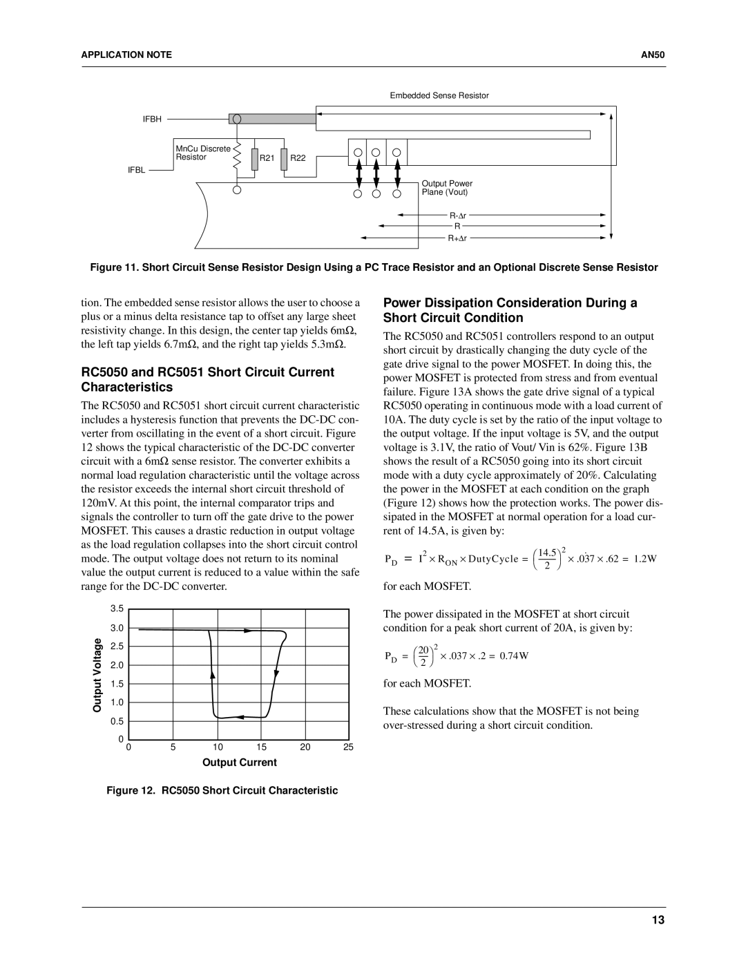
IFBH
IFBL
MnCu Discrete Resistor
| Embedded Sense Resistor |
R21 | R22 |
| Output Power |
| Plane (Vout) |
| |
| R |
| R+Δr |
Figure 11. Short Circuit Sense Resistor Design Using a PC Trace Resistor and an Optional Discrete Sense Resistor
tion. The embedded sense resistor allows the user to choose a plus or a minus delta resistance tap to offset any large sheet resistivity change. In this design, the center tap yields 6mΩ, the left tap yields 6.7mΩ, and the right tap yields 5.3mΩ.
RC5050 and RC5051 Short Circuit Current Characteristics
The RC5050 and RC5051 short circuit current characteristic includes a hysteresis function that prevents the
| 3.5 | |
Voltage | 3.0 | |
2.5 | ||
| ||
Output | 2.0 | |
1.5 | ||
| ||
| 1.0 |
0.5
0
0 | 5 | 10 | 15 | 20 | 25 |
Power Dissipation Consideration During a Short Circuit Condition
The RC5050 and RC5051 controllers respond to an output short circuit by drastically changing the duty cycle of the gate drive signal to the power MOSFET. In doing this, the power MOSFET is protected from stress and from eventual failure. Figure 13A shows the gate drive signal of a typical RC5050 operating in continuous mode with a load current of 10A. The duty cycle is set by the ratio of the input voltage to the output voltage. If the input voltage is 5V, and the output voltage is 3.1V, the ratio of Vout/ Vin is 62%. Figure 13B shows the result of a RC5050 going into its short circuit mode with a duty cycle approximately of 20%. Calculating the power in the MOSFET at each condition on the graph (Figure 12) shows how the protection works. The power dis- sipated in the MOSFET at normal operation for a load cur- rent of 14.5A, is given by:
P |
| = I | 2 | ⋅ R |
| ⋅ DutyCycle = | | 14.5 2 | ˙ | ⋅ .62 = 1.2W |
D |
| ON | | ⋅ .037 | ||||||
|
|
|
|
| 2 |
|
|
for each MOSFET.
The power dissipated in the MOSFET at short circuit condition for a peak short current of 20A, is given by:
P |
| = | 20 | 2 | ⋅ .037 | ⋅ .2 = 0.74W |
D |
| |||||
|
| 2 |
|
|
|
for each MOSFET.
These calculations show that the MOSFET is not being
Output Current
Figure 12. RC5050 Short Circuit Characteristic
13