FARGO electronic CD Color Printer manual TABLE A-2 Serial Interface Pin Assignments, Pin Number

Models: CD Color Printer

1 53
Download 53 pages 4.02 Kb
Page 50
Image 50
C. MINI 8-PIN SERIAL INTERFACE

C. MINI 8-PIN SERIAL INTERFACE

The mini 8-pin serial interface connector is the standard interface used by Macintosh. The printerÕs serial port mates with a standard computer to printer serial cable. For best results, always use a high-quality serial cable which is less than 6 feet in length.

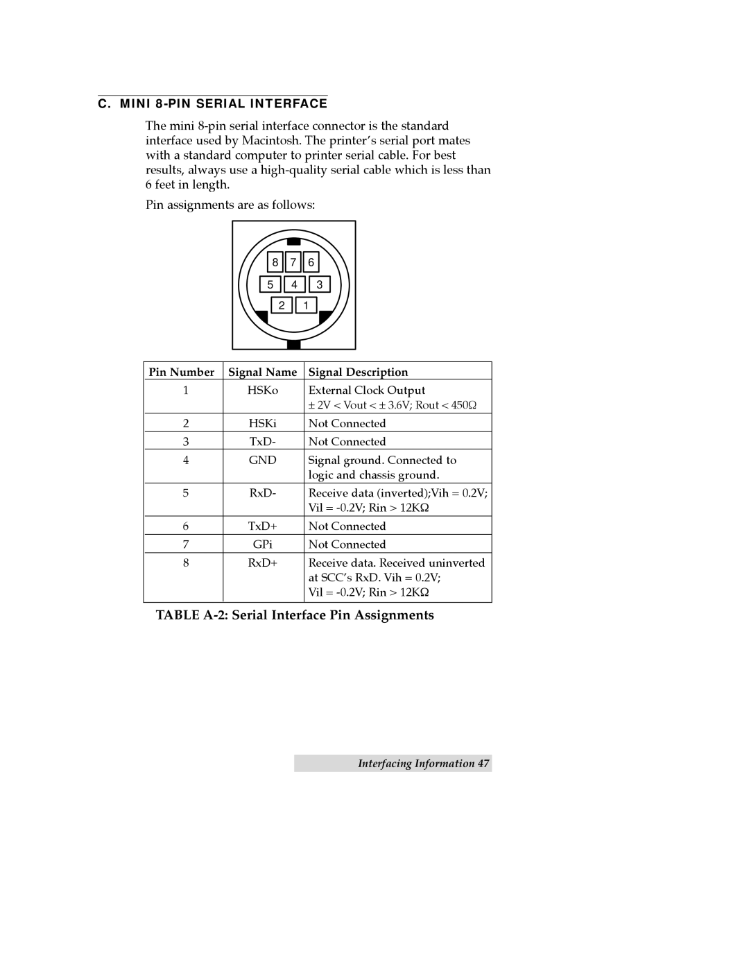
Pin assignments are as follows:

8 Pin NumberSignal Name 7 Signal DescriptionTABLE A-2: Serial Interface Pin Assignments 6

5Manual backgroundManual background

2

4Manual backgroundManual background

Manual backgroundManual background 1

3

Pin Number

Signal Name

Signal Description

1

HSKo

External Clock Output


± 2V < Vout < ± 3.6V; Rout < 450½

2

HSKi

Not Connected

3

TxD-

Not Connected

4

GND

Signal ground. Connected to


logic and chassis ground.

5RxD- Receive data (inverted);Vih = 0.2V;

Vil = -0.2V; Rin > 12K½

6

TxD+

Not Connected

7

GPi

Not Connected

8

RxD+

Receive data. Received uninverted


at SCCÕs RxD. Vih = 0.2V;


Vil = -0.2V; Rin > 12K½

TABLE A-2: Serial Interface Pin Assignments

Interfacing Information 47

Page 50
Image 50
FARGO electronic CD Color Printer TABLE A-2 Serial Interface Pin Assignments, C. MINI 8-PINSERIAL INTERFACE, Pin Number