1750
Operators Manual
|
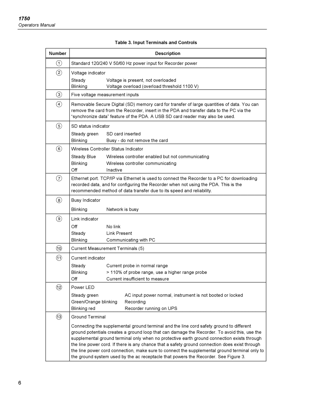
| Table 3. Input Terminals and Controls |
|
|
|
Number |
| Description |
|
| |
A | Standard 120/240 V 50/60 Hz power input for Recorder power | |
|
|
|
B | Voltage indicator |
|
| Steady | Voltage is present, not overloaded |
| Blinking | Voltage overload (overload threshold 1100 V) |
C | Five voltage measurement inputs | |
|
| |
D | Removable Secure Digital (SD) memory card for transfer of large quantities of data. You can | |
| remove the card from the Recorder, insert in the PDA and transfer data to the PC via the | |
| “synchronize data” feature of the PDA. A USB SD card reader may also be used. | |
|
| |
E | SD status indicator | |
| Steady green | SD card inserted |
| Blinking | Busy - do not remove the card |
F | Wireless Controller Status Indicator | |
| Steady Blue | Wireless controller enabled but not communicating |
| Blinking | Wireless controller communicating |
| Off | Inactive |
G | Ethernet port. TCP/IP via Ethernet is used to connect the Recorder to a PC for downloading | |
| recorded data, and for configuring the Recorder when not using the PDA. This is the | |
| recommended method of data transfer due to its speed and reliability. | |
|
|
|
H | Busy Indicator |
|
| Blinking | Network is busy |
|
|
|
I | Link indicator |
|
| Off | No link |
| Steady | Link Present |
| Blinking | Communicating with PC |
J | Current Measurement Terminals (5) | |
|
|
|
K | Current indicator |
|
| Steady | Current probe in normal range |
| Blinking | > 110% of probe range, use a higher range probe |
| Off | Current insufficient to measure |
L | Power LED |
|
| Steady green | AC input power normal, instrument is not booted or locked |
| Green/Orange blinking Recording | |
| Blinking red | Recorder running on UPS |
M | Ground Terminal |
|
| Connecting the supplemental ground terminal and the line cord safety ground to different | |
| ground potentials creates a ground loop that can damage the Recorder. To avoid this, use the | |
| supplemental ground terminal only when no protective earth ground connection exists through | |
| the line power cord. If there is any chance that a safety ground connection does exist through | |
| the line power cord connection, make sure to connect the supplemental ground terminal only to | |
| the ground system used by the ac receptacle that powers the Recorder. See Figure 3. | |
|
|
|
6
