Front panel LEDs and connectors |
|
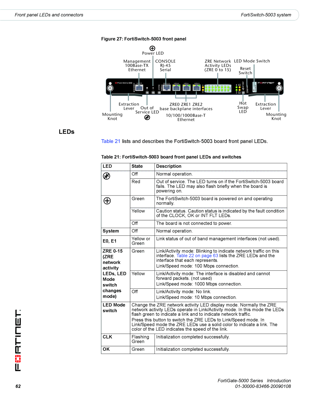
Figure 27: FortiSwitch-5003 front panel
Power LED |
|
| |
Management | CONSOLE | ZRE Network | LED Mode Switch |
Activity LEDs | Reset | ||
Ethernet | Serial | (ZRE 0 to 15) | |
|
|
| Switch |
MANAGEMENT | E T H O |
|
| R S 2 3 2 |
| Z R E 0 |
| Z R E 1 |
| Z R E 2 | E0 E1 |
|
|
|
| ||||||||||
|
|
| SYSTEM | CONSOLE |
|
|
|
|
|
|
|
|
|
|
|
|
|
|
| 14 15 | 12 13 | 10 11 | 8 9 | ||
|
|
|
|
|
|
|
|
|
|
|
|
|
|
|
|
|
| ||||||||
|
|
|
|
|
|
|
|
|
|
|
|
|
|
|
|
|
|
| |||||||
Extraction | ZRE0 ZRE1 ZRE2 | |
Lever | Out of | base backplane interfaces |
Mounting | Service LED | |
| ||
Knot |
| Ethernet |
7 | 5 | 3 | 1 |
| OK | INT FLT | HOT SWAP | RESET |
|
|
|
| ZRE |
|
| ||
6 | 4 | 2 | 0 |
| CLK | EXT FLT |
|
|
Hot
Swap
LED
LED MODE
Extraction
Lever
Mounting
Knot
LEDs
Table 21 lists and describes the
Table 21:
LED | State | Description | |||||
|
|
|
|
|
|
|
|
|
|
|
|
|
| Off | Normal operation. |
|
|
|
|
|
| ||
|
|
|
|
|
|
|
|
|
|
|
|
|
| Red | Out of service. The LED turns on if the |
|
|
|
|
|
|
| fails. The LED may also flash briefly when the board is |
|
|
|
|
|
|
| powering on. |
|
|
|
|
|
|
|
|
|
|
|
|
|
| Green | The |
|
|
|
|
|
| ||
|
|
|
|
|
|
| normally. |
|
|
|
|
|
|
| |
|
|
|
|
|
|
|
|
|
|
|
|
|
| Yellow | Caution status. Caution status is indicated by the fault condition |
|
|
|
|
|
|
| of the CLOCK, OK or INT FLT LEDs. |
|
|
|
|
|
|
|
|
|
|
|
|
|
| Off | The board is not connected to power. |
|
|
|
|
|
|
|
|
System | Off | Normal operation. | |||||
|
|
|
|
|
|
|
|
E0, E1 | Yellow or | Link status of out of band management interfaces (not used). | |||||
Green |
| ||||||
|
|
|
|
|
|
| |
|
|
|
|
|
|
|
|
ZRE | Green | Link/Activity mode: Blinking to indicate network traffic on this | |||||
(ZRE |
| interface. Table 22 on page 63 lists the ZRE LEDs and the | |||||
network |
| interface that each represents. | |||||
| Link/Speed mode: 100 Mbps connection. | ||||||
activity |
| ||||||
|
| ||||||
LEDs, LED | Yellow | Link/Activity mode: The interface is disabled and cannot | |||||
Mode |
| forward packets. (not used) | |||||
switch |
| Link/Speed mode: 1000 Mbps connection. | |||||
changes | Off | Link/Activity mode: No link. | |||||
mode) |
| Link/Speed mode: 10 Mbps connection. | |||||
|
|
|
|
|
|
|
|
LED Mode | Change the | ZRE network activity LED display mode. Normally the ZRE | |||||
switch | network activity LEDs operate in Link/Activity mode. In this mode the LEDs | ||||||
|
|
|
|
|
| flash green to indicate a link and to indicate network traffic. | |
|
|
|
|
|
| Press this button to switch the ZRE LEDs to Link/Speed mode. In | |
|
|
|
|
|
| Link/Speed mode the ZRE LEDs use a solid color to indicate a link. The | |
|
|
|
|
|
| color of the LED indicates the speed of the link. | |
|
|
|
|
|
|
|
|
CLK | Flashing | Initialization completed successfully. | |||||
|
|
|
|
|
| Green |
|
|
|
|
|
|
|
|
|
OK | Green | Initialization completed successfully. | |||||
|
|
|
|
|
|
|
|
FortiGate-5000 Series Introduction
62 |
|
