Front panel LEDs and connectors |
|
Table 16:
LED | State | Description |
|
|
|
| Solid | Indicates this interface is connected to a |
BASE 10G, 14/F8, F7, | Green | network device with the correct cable and the |
| attached network device has power. | |
F6, F5, F4, F3, F2, F1 |
| |
|
| |
(Base and Fabric 10 | Blinking | Indicates |
gigabit LEDs) | Green |
|
|
| |
| Off | No link. |
|
|
|
HS (Hot Swap) | Blue | The |
|
| (removed from the chassis). If the HS light is blue |
|
| and no other LEDs are lit the |
|
| board has lost power |
|
|
|
| Flashing | The |
| Blue | running mode or from running mode to hot swap. |
|
| This happens when the |
|
| starting up or shutting down. |
|
|
|
| Off | Normal operation. The |
|
| contact with the chassis backplane. |
|
|
|
Base channel interfaces
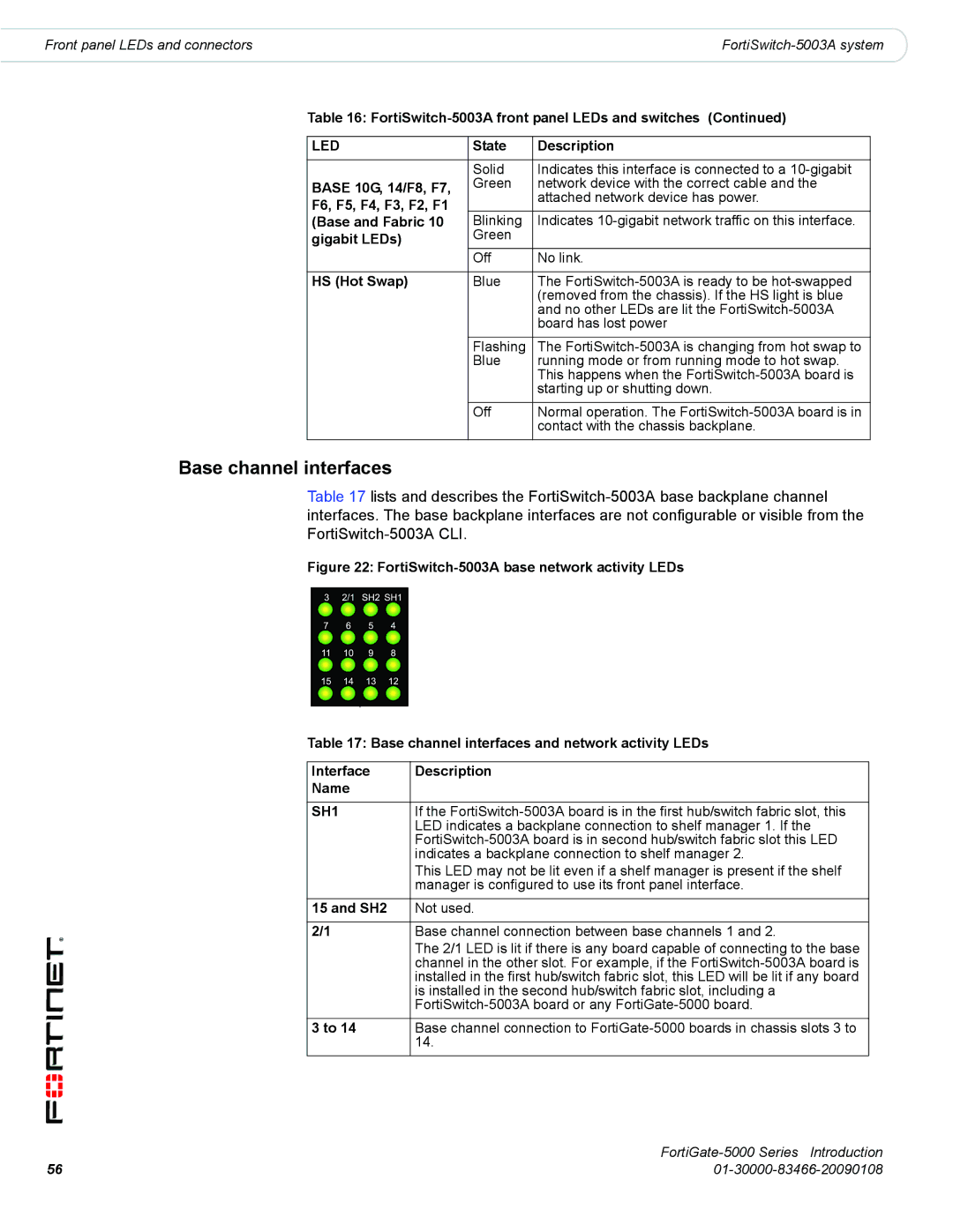
Table 17 lists and describes the
Figure 22: FortiSwitch-5003A base network activity LEDs
Table 17: Base channel interfaces and network activity LEDs
Interface | Description |
Name |
|
|
|
SH1 | If the |
| LED indicates a backplane connection to shelf manager 1. If the |
| |
| indicates a backplane connection to shelf manager 2. |
| This LED may not be lit even if a shelf manager is present if the shelf |
| manager is configured to use its front panel interface. |
|
|
15 and SH2 | Not used. |
|
|
2/1 | Base channel connection between base channels 1 and 2. |
| The 2/1 LED is lit if there is any board capable of connecting to the base |
| channel in the other slot. For example, if the |
| installed in the first hub/switch fabric slot, this LED will be lit if any board |
| is installed in the second hub/switch fabric slot, including a |
| |
|
|
3 to 14 | Base channel connection to |
| 14. |
|
|
|
|
56 |
