Front panel LEDs and connectors |
The
Front panel LEDs and connectors
From the
LEDs
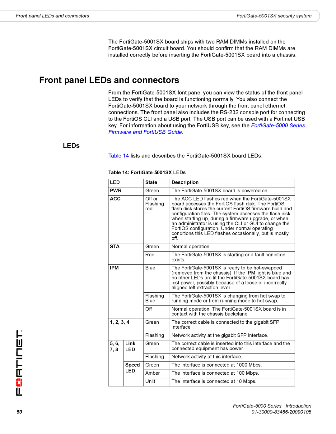
Table 14 lists and describes the FortiGate-5001SX board LEDs.
Table 14: FortiGate-5001SX LEDs
LED |
| State | Description |
|
|
|
|
PWR |
| Green | The |
|
|
|
|
ACC |
| Off or | The ACC LED flashes red when the |
|
| Flashing | board accesses the FortiOS flash disk. The FortiOS |
|
| red | flash disk stores the current FortiOS firmware build and |
|
|
| configuration files. The system accesses the flash disk |
|
|
| when starting up, during a firmware upgrade, or when |
|
|
| an administrator is using the CLI or GUI to change the |
|
|
| FortiOS configuration. Under normal operating |
|
|
| conditions this LED flashes occasionally, but is mostly |
|
|
| off. |
STA |
| Green | Normal operation. |
|
|
|
|
|
| Red | The |
|
|
| exists. |
IPM |
| Blue | The |
|
|
| (removed from the chassis). If the IPM light is blue and |
|
|
| no other LEDs are lit the |
|
|
| lost power, possibly because of a loose or incorrectly |
|
|
| aligned left extraction lever. |
|
| Flashing | The |
|
| Blue | running mode or from running mode to hot swap. |
|
| Off | Normal operation. The |
|
|
| contact with the chassis backplane. |
1, 2, 3, 4 | Green | The correct cable is connected to the gigabit SFP | |
|
|
| interface. |
|
| Flashing | Network activity at the gigabit SFP interface. |
|
|
|
|
5, 6, | Link | Green | The correct cable is inserted into this interface and the |
7, 8 | LED |
| connected equipment has power. |
|
| Flashing | Network activity at this interface. |
|
|
|
|
| Speed | Green | The interface is connected at 1000 Mbps. |
| LED |
|
|
| Amber | The interface is connected at 100 Mbps. | |
|
| ||
|
|
|
|
|
| Unlit | The interface is connected at 10 Mbps. |
|
|
|
|
|
|
50 |
