|
|
|
Front panel LEDs and connectors |
Table 25: FortiController-5208 board LEDs (Continued)
LED |
| State | Description |
|
|
|
|
CONTROL | Green | The control LEDs display the fabric backplane | |
|
|
| connections of the |
|
|
| an optional secondary |
|
|
| and all the 5005 boards, over which management |
|
|
| communication is sent. LED 1 is for the |
|
|
| |
|
|
| through 14 are for connections to the corresponding |
|
|
| slots in a 5050 or 5140. LEDs 15 and 16 are for |
|
|
| future use. |
|
|
|
|
|
| Flashing | Management communication activity on the fabric |
|
|
| backplane connection. |
|
|
|
|
1, 2, 3, 4 |
| Green | The correct cable is connected to the gigabit SFP |
|
|
| interface. |
|
|
|
|
|
| Flashing | Network activity at the gigabit SFP interface. |
|
|
|
|
IPM |
| Blue | The |
|
|
| swapped (removed from the chassis). If the IPM |
|
|
| light is blue and no other LEDs are lit the |
|
|
| |
|
|
| “Inserting a |
|
|
| chassis” on page 10 for more information. |
|
|
|
|
|
| Flashing | The |
|
| Blue | to running mode or from running mode to hot swap. |
|
|
|
|
|
| Off | Normal operation. The |
|
|
| in contact with the chassis backplane. |
|
|
|
|
MANAGEMENT | Link | Amber | The correct cable is inserted into this interface and |
| LED |
| the connected equipment has power. |
|
| Flashing | Network activity at this interface. |
|
|
|
|
| Speed | Green | The interface is connected at 1000 Mbps. |
| LED |
|
|
| Amber | The interface is connected at 100 Mbps. | |
|
| ||
|
|
|
|
|
| Unlit | The interface is connected at 10 Mbps. |
|
|
|
|
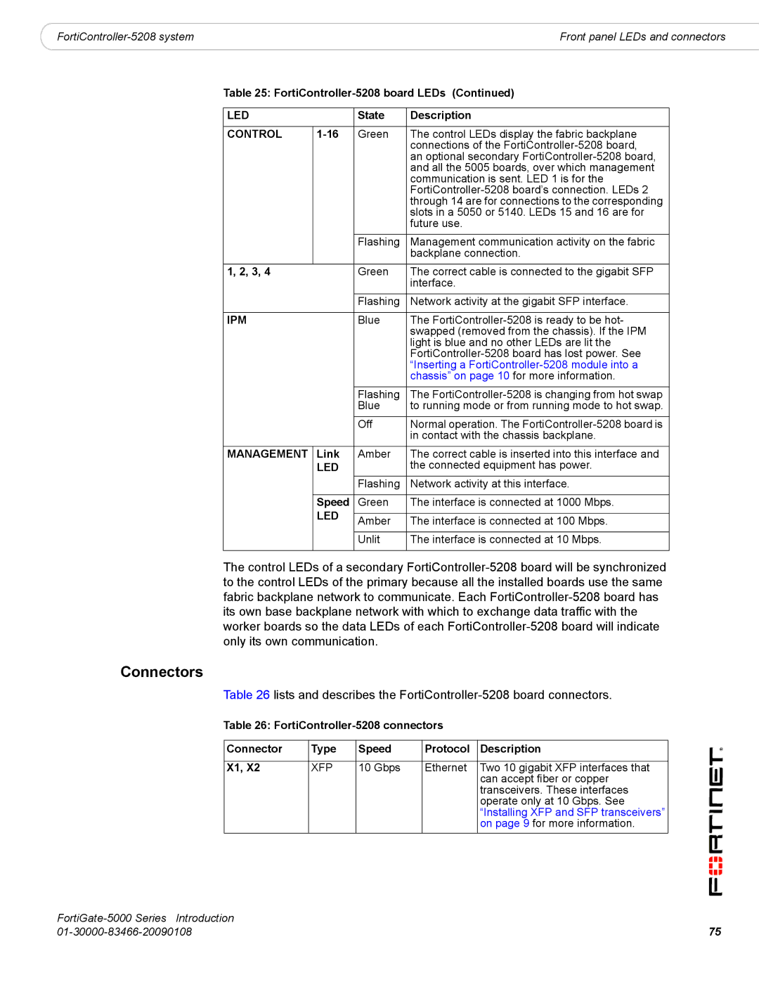
The control LEDs of a secondary
Connectors
Table 26 lists and describes the
Table 26:
Connector | Type | Speed | Protocol | Description |
|
|
|
|
|
X1, X2 | XFP | 10 Gbps | Ethernet | Two 10 gigabit XFP interfaces that |
|
|
|
| can accept fiber or copper |
|
|
|
| transceivers. These interfaces |
|
|
|
| operate only at 10 Gbps. See |
|
|
|
| “Installing XFP and SFP transceivers” |
|
|
|
| on page 9 for more information. |
| |
75 |
