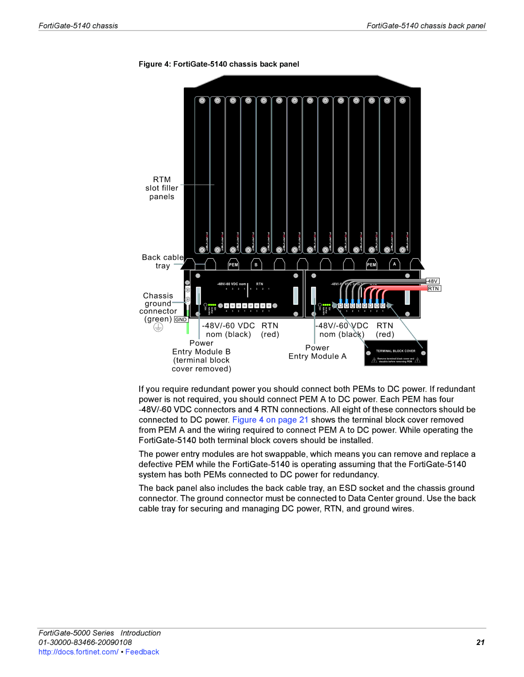
Figure 4: FortiGate-5140 chassis back panel
RTM
slot filler
panels
Back cable
tray
PEM | B | PEM | A |
|
|
|
|
|
| RTN |
| |
| 4 | 3 | 2 | 1 | 4 | 3 | 2 | 1 |
Chassis |
|
|
|
|
|
|
|
|
ground | HS operate Alarm HS |
|
|
|
|
|
|
|
connector | 3 | 2 | 1 | 4 | 3 | 2 | 1 | |
| 4 | |||||||
(green) |
|
|
|
|
|
|
|
|
Power
Entry Module B (terminal block cover removed)
| RTN |
| |||||
4 | 3 | 2 | 1 | 4 | 3 | 2 | 1 |
HS operate Alarm HS | 3 | 2 | 1 | 4 | 3 | 2 | 1 |
4 | |||||||
| RTN | ||||||
nom (black) |
| (red) | |||||
Power |
|
|
|
|
| TERMINAL BLOCK COVER | |
Entry Module A |
|
|
|
|
| Remove terminal block cover and | |
|
|
|
|
|
|
| decable before removing PEM. |
If you require redundant power you should connect both PEMs to DC power. If redundant power is not required, you should connect PEM A to DC power. Each PEM has four
The power entry modules are hot swappable, which means you can remove and replace a defective PEM while the
The back panel also includes the back cable tray, an ESD socket and the chassis ground connector. The ground connector must be connected to Data Center ground. Use the back cable tray for securing and managing DC power, RTN, and ground wires.
| |
21 | |
http://docs.fortinet.com/ • Feedback |
|