CONNECTIONS
DIGITAL SIGNAL CONNECTION
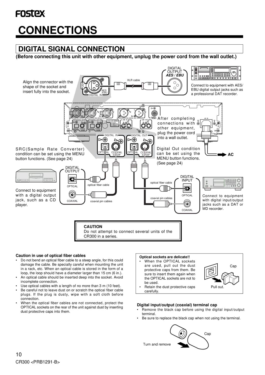
(Before connecting this unit with other equipment, unplug the power cord from the wall outlet.)
Align the connector with the shape of the socket and insert fully into the socket.
PUSH
AES /EBU
DIGITAL IN
XLR cable
DIGITAL
OUTPUT
AES / EBU
Connect to equipment with AES/ EBU digital output jacks such as a professional DAT recorder.
| R | L | R | L |
|
|
|
|
PUSH | PUSH | PUSH |
|
|
|
|
|
|
AES |
|
|
|
|
|
|
|
|
/ EBU |
| DIGITAL OUT |
| LINE IN | LINE OUT | PARALLEL | ||
DIGITAL IN |
|
|
| REMOTE | After completing | |||
DIGITAL IN |
| BALANCED IN |
| BALANCED OUT |
|
|
| |
|
| R L | R L |
|
| connections with | ||
|
|
| 2. HOT ( + ) |
|
| |||
|
|
| 1. GND |
|
|
| ||
|
|
| 3. COLD ( - ) |
|
|
|
| other equipment, |
OPTICAL COAXIAL | OPTICAL COAXIAL |
|
|
|
|
| ||
S/PDIF |
| S/PDIF |
|
|
|
|
| plug the power cord |
|
| DIGITAL IN | DIGITAL OUT |
|
| |||
|
|
|
| into a wall outlet. | ||||
|
|
|
|
|
|
|
| |
S R C ( S a m p l e R a t e C o n v e r t e r ) |
| OPTICAL | COAXIAL | OPTICAL | COAXIAL | Digital Out condition | ||
condition can be set using the MENU |
| can be set using the | ||||||
|
| S/PDIF |
| S/PDIF |
| |||
button functions. (See page 24) |
|
|
|
|
|
| MENU button functions. | |
|
|
|
|
|
|
| (See page 24) | |
| DIGITAL |
|
| OUTPUT |
|
|
| DIGITAL |
|
| INPUT |
|
| optical fiber cable |
| OPTICAL | optical fiber cable |
|
| |
Connect to equipment |
|
|
with a digital output |
| OPTICAL |
jack, such as a CD | COAXIAL | coaxial pin cables |
coaxial pin cables | ||
player. |
|
|
|
| COAXIAL |
AC IN
![]()
![]() AC
AC
Connect to equipment with digital input/output jacks such as a DAT or MD recorder.
CAUTION
Do not attempt to connect several units of the CR300 in a series.
Caution in use of optical fiber cables
•Do not bend an optical fiber cable to a steep angle, for this could damage the cable. Be specially careful when mounting the unit in a rack, etc. When an optical cable is stored in the form of a loop, the loop should have a diameter larger than 15 cm (6 in.).
•An optical cable should be inserted deep into the socket. Avoid incomplete connection.
•Use optical cables with a length of no more than 3 m (10 feet).
•Be careful not to leave dust on or scratch the optical fiber cable plugs. If the plug is dusty, wipe with a soft cloth before connection.
•When the optical fiber cables are not connected, protect the OPTICAL sockets on the rear of the unit against dust by inserting dust protective caps into them.
Optical sockets are delicate!!
•When the OPTICAL sockets
are used, pull out the dust | Cap |
protective caps from them. Be |
|
sure to insert them again when |
|
the OPTICAL sockets are not to |
|
be used. |
|
• Retain the dust protective caps | Pull out. |
carefully. |
|
Digital input/output (coaxial) terminal cap
•Remove the black cap before using the digital input/output terminal.
•Be sure to replace the black cap when not using the terminal.
Cap
Turn and remove
10
CR300