White Paper ⏐ Issue: October 2006 ⏐ Integration of BX600 SB9 Switches in Cisco Networks | Page 6 / 47 |
2.2.3 Configuration
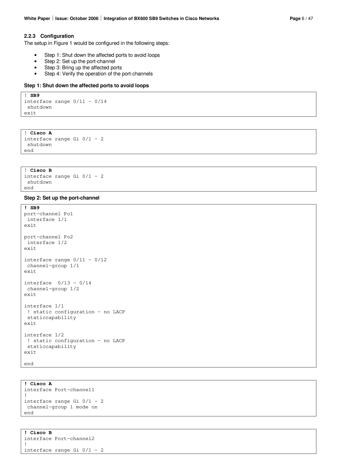
The setup in Figure 1 would be configured in the following steps:
∙Step 1: Shut down the affected ports to avoid loops
∙Step 2: Set up the
∙Step 3: Bring up the affected ports
∙Step 4: Verify the operation of the
Step 1: Shut down the affected ports to avoid loops
!SB9
interface range 0/11 – 0/14 shutdown
exit
!Cisco A
interface range Gi 0/1 – 2 shutdown
end
!Cisco B
interface range Gi 0/1 – 2 shutdown
end
Step 2: Set up the port-channel
! SB9
interface 1/1 exit
exit
interface range 0/11 – 0/12
exit
interface 0/13 – 0/14
exit
interface 1/1
!static configuration – no LACP staticcapability
exit
interface 1/2
!static configuration – no LACP staticcapability
exit
end
! Cisco A
interface
!
interface range Gi 0/1 - 2
end
! Cisco B
interface
!
interface range Gi 0/1 - 2
