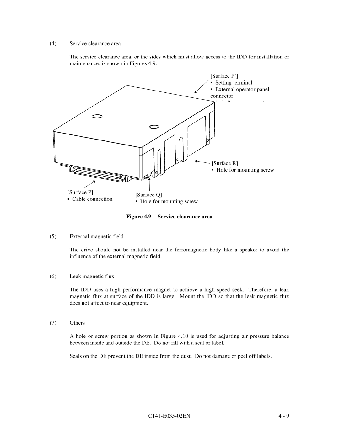
(4)Service clearance area
The service clearance area, or the sides which must allow access to the IDD for installation or maintenance, is shown in Figures 4.9.
[Surface P’]
• Setting terminal
• External operator panel connector
• Spindle sync connector
| [Surface R] | |
| • Hole for mounting screw | |
[Surface P] | [Surface Q] | |
• Cable connection | ||
• Hole for mounting screw | ||
| ||
| Figure 4.9 Service clearance area |
(5)External magnetic field
The drive should not be installed near the ferromagnetic body like a speaker to avoid the influence of the external magnetic field.
(6)Leak magnetic flux
The IDD uses a high performance magnet to achieve a high speed seek. Therefore, a leak magnetic flux at surface of the IDD is large. Mount the IDD so that the leak magnetic flux does not affect to near equipment.
(7)Others
A hole or screw portion as shown in Figure 4.10 is used for adjusting air pressure balance between inside and outside the DE. Do not fill with a seal or label.
Seals on the DE prevent the DE inside from the dust. Do not damage or peel off labels.
4 - 9 |
