5.3Setting Terminals
The user must set the following terminals and SCSI terminating resistor before installing the IDD in the system.
∙ Setting terminal: | CN6, CN7 |
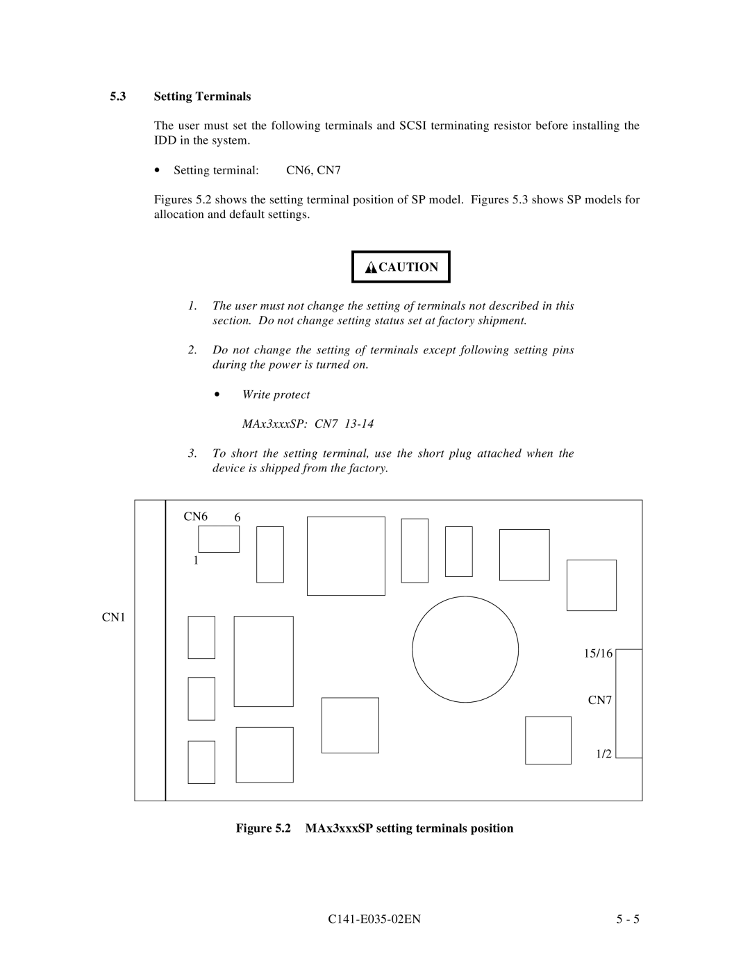
Figures 5.2 shows the setting terminal position of SP model. Figures 5.3 shows SP models for allocation and default settings.
![]() CAUTION
CAUTION
1.The user must not change the setting of terminals not described in this section. Do not change setting status set at factory shipment.
2.Do not change the setting of terminals except following setting pins during the power is turned on.
∙Write protect MAx3xxxSP: CN7
3.To short the setting terminal, use the short plug attached when the device is shipped from the factory.
CN6 6
1
CN1
15/16
CN7
1/2
Figure 5.2 MAx3xxxSP setting terminals position
5 - 5 |