|
|
|
| 254.0 to 457.2 mm |
| |
|
|
|
| (10 to 18 inch) |
| |
|
|
| 127.0 to 304.8 mm | 101.6 to 152.4 mm | ||
|
|
| (5 to 12 inch) |
| (4 to 6 inch) |
|
Pin 40 (Ground) |
|
|
|
| ||
|
|
| open |
|
|
|
Pin 34 |
|
|
|
|
| |
Pin 30 (Ground) |
|
| Pin 34 contact |
| ||
Pin 26 (Ground) | Symbolizes Pin 34 | |||||
Conductor being cut |
|
| ||||
Pin 24 (Ground) |
|
|
|
| ||
Pin 22 | (Ground) |
|
|
|
| |
Pin 19 | (Ground) | Position 1 |
|
|
| |
Pin | 2 | (Ground) |
|
|
| |
|
|
|
| |||
|
| System Board |
|
| Connector 1 | Connector 2 |
|
| Connector |
|
|
|
|
|
|
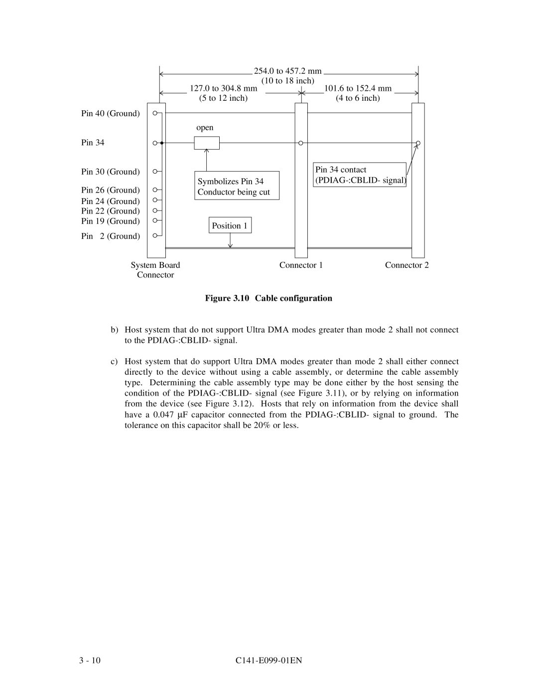
| Figure 3.10 | Cable configuration |
| |
b)Host system that do not support Ultra DMA modes greater than mode 2 shall not connect to the
c)Host system that do support Ultra DMA modes greater than mode 2 shall either connect directly to the device without using a cable assembly, or determine the cable assembly type. Determining the cable assembly type may be done either by the host sensing the condition of the
3 - 10 |
|