Facsimile Receiver
First E D I T I O N
Safety Instructions
Safety Instructions for the Installer
Table of Contents
Navtex Operation Navnet
Appendix
Features
Foreword
Word to the Owner of the FAX-30
NavNet
Operational Characteristics
Vii
General
Viii
System Configuration
Network installation
Network installation
Facsimile Receiver
PC installation
Equipment Lists
Standard supply
Name Type Code No Qty Remarks
Optional supply
Xii
Name Type Code No Remarks
Controls
OVERVIEW, Setup
Overview, Setup NavNet
Controls
Select sentence window
Preparations for using the FAX-30
Accessing the FAX mode
FAX-30, top view
Display selection window
Standby display
Choosing the receive mode
Receive mode setup screen
RX mode options
RX notice options
Receive notification
Overview, Setup PC
Accessing the FAX-30 top display
Facsimile receiver top display
Standby displays
Logging out
RX Mode
Thumbnails of received images
FAX Operation Navnet
Automatic Receiving
Choosing channel
Fax channel setup window
Zone options
Station options Example stations of northwest pacific
Frequency entry window
Channel options Example JMH/Tokyo
Previewing image being received
Stopping automatic receiving
Facsimile receiving display
Manually Starting, Stopping Receiving
Manually starting receiving
Start RX options
Wrong speed 120 chosen instead
Wrong Speed or IOC and Image
Manually stopping receiving
Wrong speed 60 chosen instead
Timer schedule list
Timer Receiving
Setting timer receiving schedule
Timer setup screen
Station options Example N Pacific W Part
Timer schedule menu
Start time entry window
Channel options Example station JMH
IOC options
Drum speed options
Start timer options
End time entry window
Save window
Turning on/off specific timer programs
Clearing all timer programs
Clear all options
Facsimile image
Displaying Facsimile Images
Processing Facsimile Images
Phase mismatch
Example of phase mismatching
Phase entry window
Sync entry window
Phasing signal out of synchronization
Example of phasing signal out of synchronization
Noise rejection
Reverse image options
Image color
Image format
Color options
Erase image options
Erasing Facsimile Images
Zooming images
Rotating images
Preventing Erasure of Facsimile Images
Adding Facsimile Channels
FAX-30 top 2. Press the Edit WX FAX Station soft key
Edit facsimile station menu
Station options Example stations of northwest pacific
Frequency, call sign and station name entry windows
Stopping receiving
Channel setup menu
FAX Operation PC
Starting receiving
Timer program list
Setting, changing timer receiving schedule
Timer program menu
Timer Program No.2
Turning on/off specific timer programs
Top
Facsimile standby display
Phase
Sync options
Example of phasing signal out of synchronizatio
Color
Saving images
Lock options
Lock
Edit station list menu
Edit Station List
This page intentionally left blank
Receiving navtex messages
Navtex Operation Navnet
About Navtex Messages
Message categories
Navtex frequency options
Setting Up Navtex Stations, Messages, Alarms
RX setup menu
Navtex message data display
Navtex station mode options
Navtex station options
Navtex message options
Max error rate entry window
Alarm SAR MSG options
Alarm warning msg options
Previewing Incoming Navtex Messages
Navtex message selection screen
Navtex message preview display
Displaying Navtex Messages
Displaying navtex messages
Sample navtex message
Remarks on navtex messages
Displaying the Navtex Station List
Nav areas for 490 kHz navtex stations
KHz stations of nav area
Nav area selection window
Adding Navtex Stations
Edit station menu
Edit navtex station menu
Station name entry window
Station ID1 entry window
Latitude entry window
Navtex Operation PC
RX Setup
Setting Up Navtex Stations, Messages
Received messages click to display
Navtex standby display
Navtex station list
490kHz Station List
Edit station list
Cullercoats
Editing Navtex Stations
Deleting Navtex Stations
This page intentionally left blank
Check Point Action
MAINTENANCE, Troubleshooting
Maintenance
Maintenance points
Trouble Problem Remedy
Replacement of Fuse
Troubleshooting
Troubleshooting
Diagnostics NavNet
System setup menu
FAX-30 menu
Diagnostic test results
Diagnostics PC
Clearing Data NavNet
Clear memory menu
Clear all images options
Clear memory options
Clearing Data PC
FAX-30, cover opened
All Clear for technicians only
Simulation Mode
Accessing the simulation mode through NavNet
Simulation setup menu
SIMULATION§ Setup WX FAX §SIMULATION Live Navtex Simulation
Accessing the simulation mode through PC
This page intentionally left blank
Installation
Mounting dimensions of facsimile receiver FAX-30
Facsimile Receiver
General antenna connection
Wire antenna or whip antenna
Antenna wiring and preamp status
Antenna Unit
How to mount the preamp unit FAX-5
Installation of preamp unit FAX-5 option
Wiring
Wiring
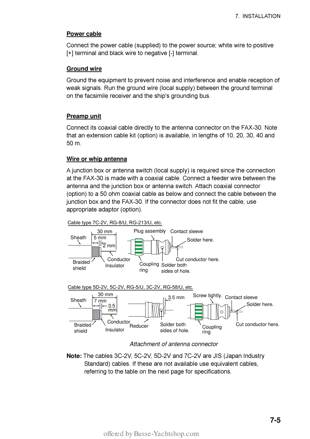
Attachment of antenna connector
Power cable
Ground wire
Wire or whip antenna
Supplying Power to the Preamp Unit
JIS cable specifications
FAX-30, top view, cover removed
Netscape Navigator Version
Browser, PC Settings
Browser settings
Internet Explorer Version
PC settings
FAX-30
IP address
AP-1
Appendix
Facsimile Stations
Facsimile station map
Zone
AP-2
Facsimile station list alphabetical order
AP-3
Location of navtex stations
Navtex Stations
Navtex stations map
AP-4
AP-5
Navtex stations list
AP-6
VII
AP-7
XII
AP-8
Soft keys
Menu Tree
NavNet menu tree
AP-9
Menu key
AP-10
PC Menu tree
AP-11
Facsimile menu tree
Navtex menu tree
AP-12
Specifications of Facsimile Receiver
This page is intentionally left blank
Packing List
FAX-30-J/E-AP
FAX-30-J/E-N
Offered by Busse-Yachtshop.com
Offered by Busse-Yachtshop.com
Offered by Busse-Yachtshop.com
Offered by Busse-Yachtshop.com
Offered by Busse-Yachtshop.com
IN-1
Index
Index
IN-2
Offered by Busse-Yachtshop.com