4.4Performance Monitor PM-30
Necessary parts: PM-30 and OP03-150 (Code no. 008-485-490)
Name | Type | Code No. | Qty |
|
|
|
|
03P9225 | 1 | ||
|
|
|
|
M3X8 C2700W | 3 | ||
|
|
|
|
Connector Assy. | 2 | ||
|
|
|
|
1.Open the processor unit. Unfasten three screws to remove the RGB Board together with its mounting plate. Unfasten the monitor cable at the RGB Board. (See Figure
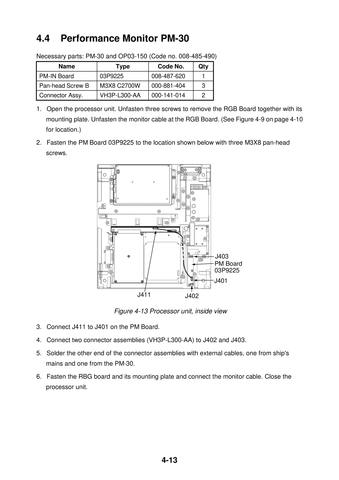
2.Fasten the PM Board 03P9225 to the location shown below with three M3X8
![]()
![]() J403
J403
![]() PM Board
PM Board ![]() 03P9225
03P9225
J401
J411J402
Figure 4-13 Processor unit, inside view
3.Connect J411 to J401 on the PM Board.
4.Connect two connector assemblies
5.Solder the other end of the connector assemblies with external cables, one from ship's mains and one from the
6.Fasten the RBG board and its mounting plate and connect the monitor cable. Close the processor unit.
