4.2.3 Final check of ARP board
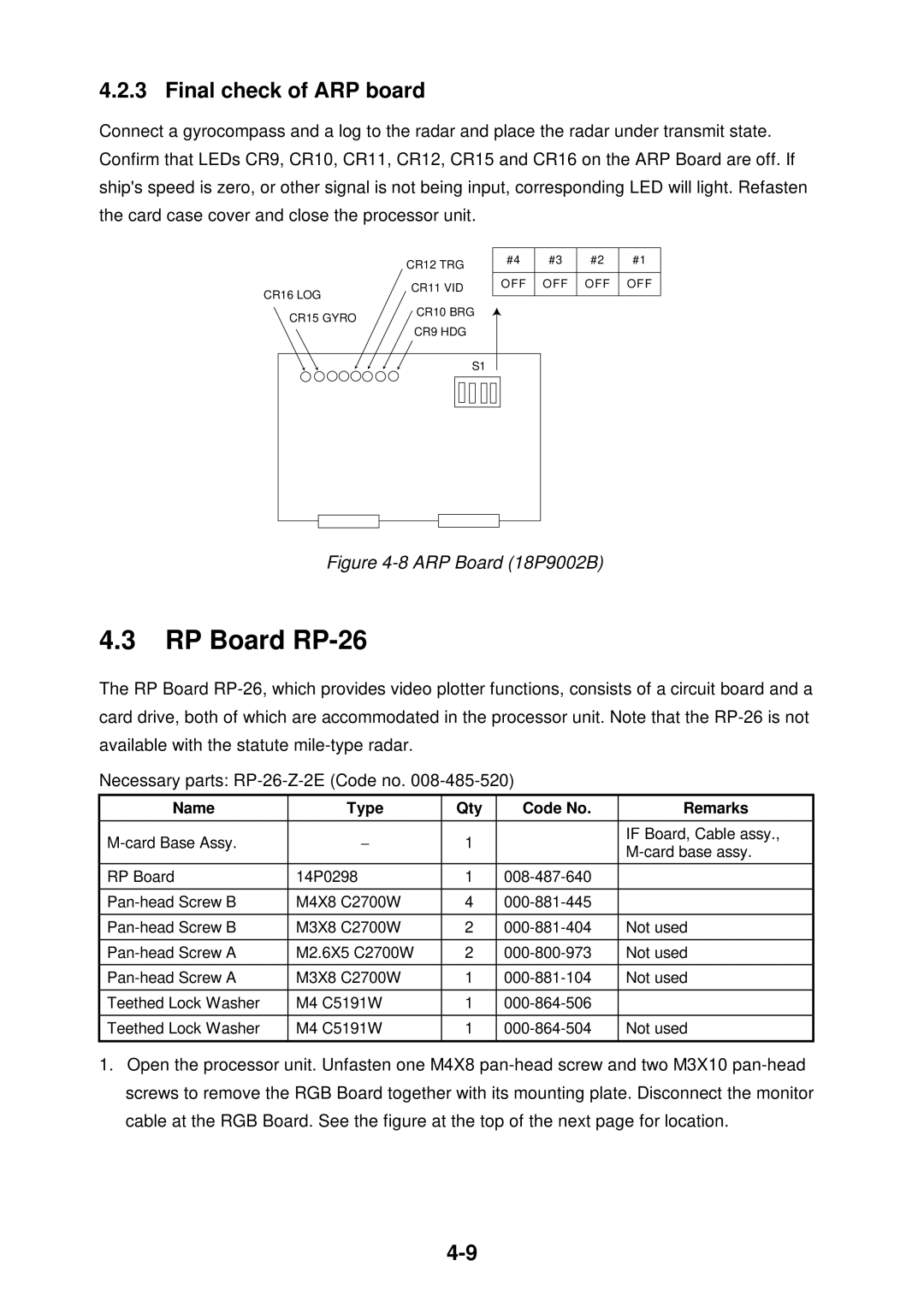
Connect a gyrocompass and a log to the radar and place the radar under transmit state. Confirm that LEDs CR9, CR10, CR11, CR12, CR15 and CR16 on the ARP Board are off. If ship's speed is zero, or other signal is not being input, corresponding LEDwill light. Refasten the card case cover and close the processor unit.
| CR12 TRG |
CR16 LOG | CR11 VID |
| |
CR15 GYRO | CR10 BRG |
| |
| CR9 HDG |
#4 | #3 | #2 | #1 |
OFF OFF OFF OFF
S1 |
Figure |
4.3RP Board RP-26
The RP Board
Necessary parts:
Name | Type | Qty | Code No. | Remarks |
|
|
|
|
|
− | 1 |
| IF Board, Cable assy., | |
| ||||
|
|
|
| |
|
|
|
|
|
RP Board | 14P0298 | 1 |
| |
|
|
|
|
|
M4X8 C2700W | 4 |
| ||
|
|
|
|
|
M3X8 C2700W | 2 | Not used | ||
|
|
|
|
|
M2.6X5 C2700W | 2 | Not used | ||
|
|
|
|
|
M3X8 C2700W | 1 | Not used | ||
|
|
|
|
|
Teethed Lock Washer | M4 C5191W | 1 |
| |
|
|
|
|
|
Teethed Lock Washer | M4 C5191W | 1 | Not used | |
|
|
|
|
|
1.Open the processor unit. Unfasten one M4X8