4.2.2 ARP board adjustment
1.Turn the GAIN, A/C SEA and A/C RAIN controls fully counterclockwise (OFF). Transmit on the 12 nm range.
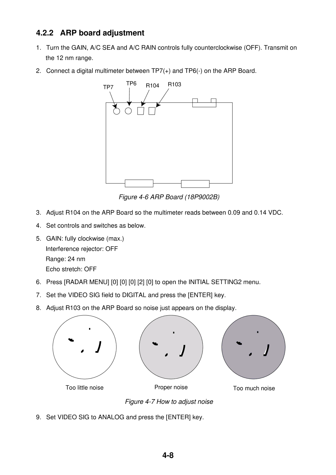
2.Connect a digital multimeter between TP7(+) and
TP6 | R104 | R103 |
TP7 |
|
|
Figure | ||
3.Adjust R104 on the ARP Board so the multimeter reads between 0.09 and 0.14 VDC.
4.Set controls and switches as below.
5.GAIN: fully clockwise (max.)
Interference rejector: OFF
Range: 24 nm
Echo stretch: OFF
6.Press [RADAR MENU] [0] [0] [0] [2] [0] to open the INITIAL SETTING2 menu.
7.Set the VIDEO SIG field to DIGITAL and press the [ENTER] key.
8.Adjust R103 on the ARP Board so noise just appears on the display.
Too little noise | Proper noise | Too much noise |
Figure 4-7 How to adjust noise
9. Set VIDEO SIG to ANALOG and press the [ENTER] key.
