14.0) INSTRUCTIONS FOR PRESSURE TEST GAUGE CONNECTION
Never operate the heater with the access panel open or removed.
The access panels must be closed tightly with all the necessary screws during operation.
Failure to do so may result in death, serious injury or property damage.
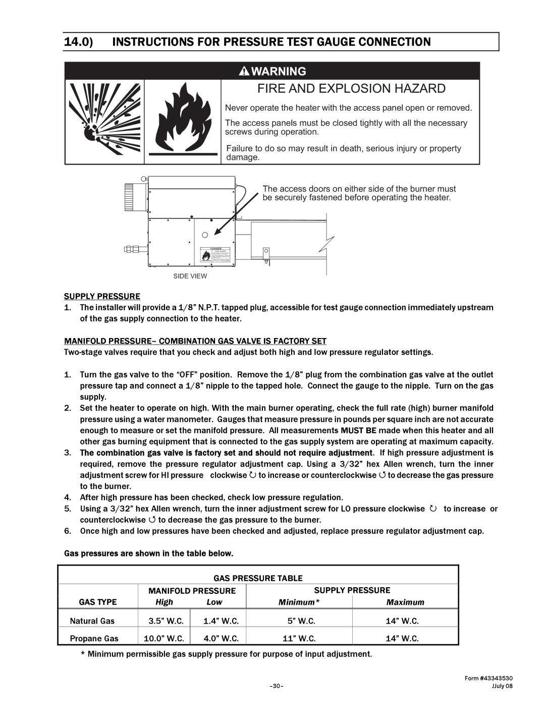
The access doors on either side of the burner must be securely fastened before operating the heater.
![]() DANGER
DANGER
FIRE HAZARD
Never operate the heater with the access panel open or removed. This access panel must be closed tightly with all the necessary screws during operation.
Failure to do so may result in death, serious injury or property damage
SIDE VIEW
SUPPLY PRESSURE
1.The installer will provide a 1/8” N.P.T. tapped plug, accessible for test gauge connection immediately upstream of the gas supply connection to the heater.
MANIFOLD PRESSURE– COMBINATION GAS VALVE IS FACTORY SET
1.Turn the gas valve to the “OFF” position. Remove the 1/8” plug from the combination gas valve at the outlet pressure tap and connect a 1/8” nipple to the tapped hole. Connect the gauge to the nipple. Turn on the gas supply.
2.Set the heater to operate on high. With the main burner operating, check the full rate (high) burner manifold pressure using a water manometer. Gauges that measure pressure in pounds per square inch are not accurate enough to measure or set the manifold pressure. All measurements MUST BE made when this heater and all other gas burning equipment that is connected to the gas supply system are operating at maximum capacity.
3.The combination gas valve is factory set and should not require adjustment. If high pressure adjustment is required, remove the pressure regulator adjustment cap. Using a 3/32” hex Allen wrench, turn the inner
| adjustment screw for HI pressure clockwise to increase or counterclockwise to decrease the gas pressure | |
| to the burner. |
|
4. | After high pressure has been checked, check low pressure regulation. |
|
5. | Using a 3/32” hex Allen wrench, turn the inner adjustment screw for LO pressure clockwise | to increase or |
| counterclockwise to decrease the gas pressure to the burner. |
|
6. | Once high and low pressures have been checked and adjusted, replace pressure regulator adjustment cap. | |
Gas pressures are shown in the table below.
GAS PRESSURE TABLE
| MANIFOLD PRESSURE | SUPPLY PRESSURE | ||
GAS TYPE | High | Low | Minimum* | Maximum |
Natural Gas | 3.5” W.C. | 1.4” W.C. | 5” W.C. | 14” W.C. |
Propane Gas | 10.0” W.C. | 4.0” W.C. | 11” W.C. | 14” W.C. |
* Minimum permissible gas supply pressure for purpose of input adjustment.
| Form #43343530 |
JJuly 08 |