19.0) SEQUENCE OF OPERATION
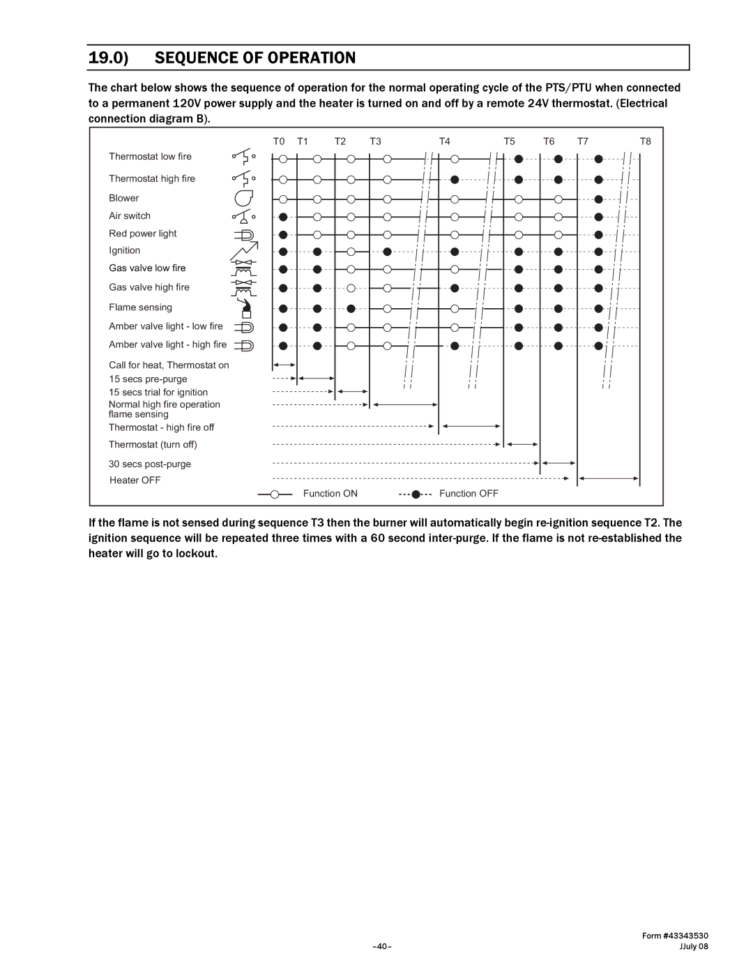
The chart below shows the sequence of operation for the normal operating cycle of the PTS/PTU when connected to a permanent 120V power supply and the heater is turned on and off by a remote 24V thermostat. (Electrical connection diagram B).
Thermostat low fire
Thermostat high fire
Blower
Air switch
Red power light
Ignition
Gas valve low fire
Gas valve high fire
Flame sensing
Amber valve light - low fire Amber valve light - high fire
Call for heat, Thermostat on 15 secs
15 secs trial for ignition
Normal high fire operation flame sensing
Thermostat - high fire off Thermostat (turn off)
30 secs
T0 | T1 | T2 | T3 |
Function ON
T4 | T5 | T6 | T7 | T8 |
Function OFF |
|
|
|
|
If the flame is not sensed during sequence T3 then the burner will automatically begin
| Form #43343530 |
JJuly 08 |