COMMON VENTING OF MULTIPLE HEATERS IN CONFINED SPACES IS PROHIBITED. If any heater connected to a common vent system for multiple heaters is found inoperative, the heater should be disconnected from the vent system and its entrance into the vent system capped.
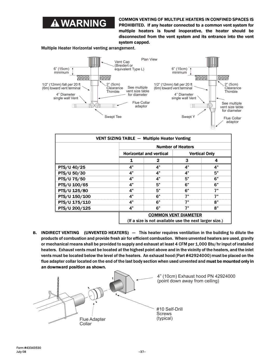
Multiple Heater Horizontal venting arrangement.
6” (15cm) minimum
1/2” (12mm) fall per 20 ft
(6m) toward vent terminal ![]()
4” Diameter
single wall Vent ![]()
| Vent Cap | Plan View |
| ||||||||||
|
|
|
|
|
|
|
|
|
| ||||
| (Breidert or | 6” (15cm) |
|
|
|
|
|
| |||||
| equivalent Type L) |
|
|
|
|
|
| ||||||
|
|
|
|
|
| minimum |
|
|
|
|
|
| |
2” (5cm) |
|
| 1/2” (12mm) fall per 20 ft |
| |||||||||
Clearance | See multiple | (6m) toward vent terminal |
| ||||||||||
Thimble | vent size table | 4” Diameter |
| ||||||||||
|
|
|
| for diameter |
| ||||||||
|
|
|
|
|
| single wall Vent |
| ||||||
|
|
|
|
| Flue Collar |
| |||||||
|
|
|
|
|
|
|
|
|
|
|
|
| |
|
|
|
|
| adaptor |
|
|
|
|
|
|
|
|
|
|
|
|
|
|
|
|
|
|
|
|
| |
Swept Tee |
|
| Swept Y |
| |||||||||
2” (5cm) Clearance Thimble
See multiple
vent size table
for diameter
Flue Collar ![]() adaptor
adaptor
| VENT SIZING TABLE — Multiple Heater Venting |
| |||||||
|
|
|
|
|
|
|
|
| |
|
|
|
|
| Number of Heaters |
| |||
|
| Horizontal and vertical |
| Vertical Only |
| ||||
|
|
|
|
|
|
|
|
|
|
|
|
| 1 |
| 2 | 3 |
| 4 |
|
|
|
|
|
|
|
|
|
|
|
| PTS/U 40/25 |
| 4” |
| 4” | 4” |
| 4” |
|
| PTS/U 50/30 |
| 4” |
| 4” | 4” |
| 5” |
|
| PTS/U 75/50 |
| 4” |
| 4” | 5” |
| 6” |
|
| PTS/U 100/65 |
| 4” |
| 5” | 6” |
| 6” |
|
| PTS/U 125/80 |
| 4” |
| 5” | 6” |
| 7” |
|
| PTS/U 150/100 |
| 4” |
| 6” | 7” |
| 7” |
|
| PTS/U 175/110 |
| 4” |
| 6” | 7” |
| 8” |
|
| PTS/U 200/125 |
| 4” |
| 6” | 7” |
| 8” |
|
|
|
|
|
|
|
| |||
|
|
|
|
| COMMON VENT DIAMETER |
| |||
|
| (If a size is not available use the next larger size.) |
| ||||||
B. INDIRECT VENTING (UNVENTED HEATERS) | — | This heater requires ventilation in the building to dilute the | |||||||
products of combustion and provide fresh air for efficient combustion. Where unvented heaters are used, gravity or mechanical means shall be provided to supply and exhaust at least 4 CFM per 1,000 Btu/hr input of installed heaters. Exhaust vents must be located at the highest point above and in the vicinity of the heaters, and the inlet vents must be located below the level of the heaters. An exhaust hood (Part #42924000) must be placed on the flue adapter collar located on the end of the last body section when used unvented and must be mounted only in an downward position as shown.
4” (10cm) Exhaust hood PN 42924000 (point down away from ceiling)
#10
Screws
Flue Adapter(typical)
Collar
Form #43343530 |
|
July 08 |