|
|
|
|
| 35 |
|
|
|
|
| 18 |
|
|
| |
|
|
|
| 7 |
|
|
|
|
|
|
| 52 |
| ||
|
|
|
| 3 |
| 61 |
|
|
|
|
|
|
| ||
|
|
|
|
|
|
|
|
|
|
|
|
|
| ||
|
|
|
| 23 |
|
| 6 |
|
|
|
|
|
|
| |
|
|
|
| 22 |
|
|
|
|
|
|
|
|
| ||
|
|
|
|
|
|
|
|
|
|
|
|
|
|
| |
|
|
|
|
|
|
|
|
|
|
| 36 |
|
|
|
|
|
|
|
|
| 5, 5a |
|
|
|
|
|
|
| 22c |
|
|
|
|
|
|
| 38 |
|
|
| 25 24 |
|
|
| 1 |
|
|
|
|
|
|
|
|
|
|
| 22d |
| 22b |
|
| ||
|
|
|
| 38a |
|
|
| 26a |
|
|
| 21 | |||
|
|
|
| 22a |
|
|
|
|
|
|
| 3 | |||
|
|
|
|
|
|
|
|
|
|
|
|
| 15 | ||
|
|
|
|
| 7 |
|
|
|
|
|
|
|
|
| |
|
|
|
|
|
|
|
|
|
|
|
| 45 |
|
| |
|
|
|
|
|
|
|
|
|
|
|
|
|
|
| |
|
|
|
|
| 31 |
|
|
| 2 |
|
|
|
|
|
|
|
|
|
|
| 1 |
|
|
|
|
|
|
|
|
| |
|
|
|
|
|
|
|
|
|
|
|
|
|
|
| |
|
|
|
|
|
|
|
|
|
|
|
|
| 3 |
| 3 |
|
|
|
|
|
|
|
|
|
|
|
|
|
| 20 | |
|
|
|
| 27 | 43 |
|
|
|
|
|
|
|
|
| |
|
|
|
|
|
|
|
|
|
|
|
|
|
|
| |
| 3 |
|
|
|
|
|
|
|
|
|
|
|
|
| 5 |
9a |
|
|
| 40 |
|
|
|
| 30 | 29 | 26 | 1a | 14 |
| 44 |
|
| 40a |
|
|
|
|
|
| |||||||
7 |
|
|
|
|
|
|
|
|
|
| |||||
17a | 41, 41a |
|
|
|
|
|
|
|
|
|
|
| 1a | ||
|
|
|
|
|
|
|
|
|
|
|
| ||||
|
|
| 46 |
|
|
|
|
|
|
|
|
| |||
|
|
|
|
|
| 48 |
|
|
|
|
|
|
|
| |
|
|
|
|
| 47 |
|
|
|
|
|
|
|
|
| |
| 10 | 63 | 38a | 22a |
| 57 | 9 |
|
|
| 51 |
| 56 |
| 22a |
|
|
|
|
|
|
| UN MUR LATÉRAL AÉRATION |
|
|
| Note: When venting a single | Nota: le conduit d'échappement | |||
|
|
| heater horizontally through a | d'un radiateur simple traversant | |||
|
|
| combustible outside wall the | un mur combustible doit passer | |||
|
|
| vent must pass through a 2” | dans une gaine de 2 po (Air Jet | |||
|
|
| clearance thimble (Air Jet No. | n° 4VT ou | |||
|
|
| 4VT or | ou autre gaine normalisée par | |||
|
|
| or other thimbles which are | un organisme d'essai reconnu | |||
|
|
| listed by nationally recognized | à l'échelle nationale. | |||
|
|
| testing agency. | Poser un capuchon d'évent | |||
|
|
| Attach a vent cap (Breidert No. | (Breidert n° 4L ou équivalent) | |||
|
|
| 4L or equivalent) | Longueur minimale équivalente | |||
|
|
|
|
|
|
| du tuyau d'échappement = 1,5m |
|
|
| Minimum equivalent length of | (5pi) | |||
|
|
| vent pipe = 5ft (1.5m) | Longueur maximale équivalente | |||
|
|
| Maximum equivalent length of | du tuyau d'échappement = 15m | |||
|
|
| vent pipe = 50ft (15m) | (50pi) | |||
|
|
|
|
|
|
|
|
|
|
|
|
|
|
|
|
|
|
|
|
|
|
|
|
|
|
|
|
|
|
|
|
|
|
|
|
|
|
|
|
|
|
|
|
|
|
|
|
|
|
|
|
|
|
|
|
|
|
|
|
|
|
|
|
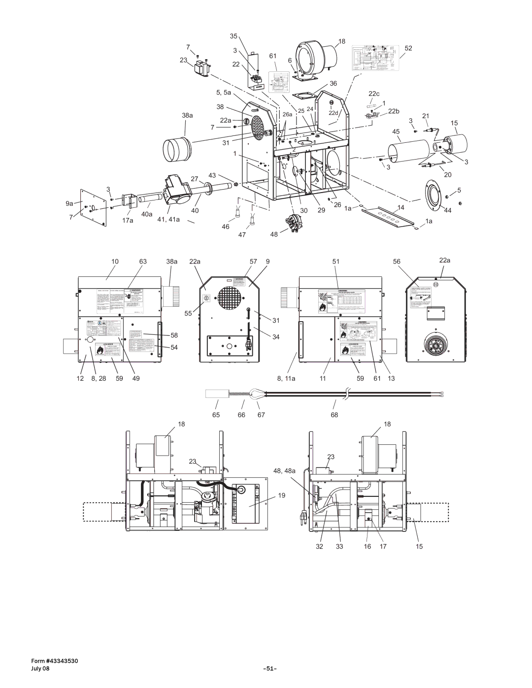
![]() DANGER
DANGER
FIRE HAZARD
Never operate the heater with the access panel open or removed. This access panel must be closed tightly with all the necessary screws during operation.
Failure to do so may result in death, serious injury or property damage
12 | 8, 28 | 59 |
![]() WARNING
WARNING
ELECTRIC SHOCK
HAZARD
Disconnect electrical supply before servicing
Failure to follow these instructions may result in death, serious injury or property damage.
THIS UNIT EQUIPPED WITH A 2 AMP IN
55
![]()
![]() 58
58 ![]() 54
54
49
18
23
HI
C
LO
![]() 31
31 ![]() 34
34
8, 11a
65 66 67
48, 48a
19
|
| TUBE INTEGRITY SAFETY SYSTEM |
|
| FRAGILE! DO NOT Lift the burner box by |
|
| these wires. |
|
| The system must be installed with tension |
| Combustible material must be located outside the clearance dimensions listed. | on the spring. |
| Failure to do so may result in death, serious injury or property damage |
|
| B | 11” |
A | A | Reflector edge. |
| C | In the event of tube failure the wire inside |
| B | |
| the sleeve will break. For safety replace | |
E |
| the entire wire assembly including the |
| F | sleeve PN 44176010 |
| C | Patent Pending |
D | D |
|
![]() DANGER
DANGER
FIRE HAZARD
Never operate the heater with the access panel open or removed. This access panel must be closed tightly with all the necessary screws during operation.
Failure to do so may result in death, serious injury or property damage
11 | 59 | 61 | 13 |
68
18
23
32 | 33 | 16 | 17 | 15 |
Form #43343530 |
|
July 08 |