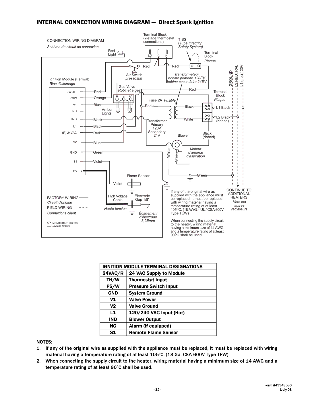
INTERNAL CONNECTION WIRING DIAGRAM — Direct Spark Ignition
CONNECTION WIRING DIAGRAM
Schéma de circuit de connexion
| Red |
|
|
| Light |
|
|
|
|
| Air Switch |
Ignition Module (Fenwal) |
|
| pressostat |
Bloc d'allumage |
|
| Gas Valve |
|
|
| |
(W)TH | Red | Robinet à gaz | |
|
| ||
P.SW | Orange | HI | C LO |
|
| ||
V1 | Blue |
|
|
NC | Amber |
|
|
Lights |
|
| |
|
|
| |
IND | Black |
|
|
L1 | Black |
|
|
(R) 24VAC | Red |
|
|
Terminal Block |
| |
TISS | ||
connections) | ||
(Tube Integrity | ||
| Safety System) |
LO C HI | Terminal |
Block | |
| Plaque |
Red | Red |
| GROUND NEUTRALL2 (hot)L1120V | |
| Transformateur |
| ||
| bobine primaire 120ÊV |
| ||
| bobine secondaire 24ÊV |
| ||
| Red |
| Terminal | |
|
|
| ||
|
|
| Block | |
Fuse 2A Fusible |
| Plaque | ||
Red | Black |
| L1 Black | |
| White |
| L2 Black | |
Transformer |
| (ribbed) | ||
|
| |||
Primary |
|
|
| |
120V |
|
|
| |
Secondary |
| Black |
| |
24V | Blower |
| ||
(ribbed) | ||||
|
| |||
V2Blue
GND Green
S1 Violet
HV |
Flame Sensor |
Violet |
White | Green | Moteur |
d'amorce | ||
|
| d'aspiration |
|
| Green |
FACTORY WIRING |
| High Voltage |
|
|
|
|
| Electrode | |||
| Cable |
|
|
|
|
|
| Gap 1/8” | |||
Circuit d'origine |
|
|
|
|
|
|
| ||||
FIELD WIRING |
| Haute tension |
|
|
|
|
|
|
|
|
|
|
|
|
|
|
|
|
|
|
| ||
|
|
|
|
|
|
|
|
|
| ||
|
|
|
|
|
|
|
|
| |||
Connexions client |
|
|
|
|
|
|
|
| Écartement | ||
|
|
|
|
|
|
|
| ||||
|
|
|
|
|
|
| |||||
|
|
|
|
|
|
|
|
| d'électrode | ||
If any of the original wire as supplied with the appliance must be replaced. It must be replaced with wiring material having a temperature rating of at least
105oC. (18 AWG. - UL / CSA 600V Type TEW)
CONTINUE TO
ADDITIONAL
HEATERS
Vers les
autres
radiateurs
MONITORING LIGHTS Lampes témoins
3,2Êmm
When connecting the supply circuit to the heater, wiring material having a minimum size of 14 AWG and a temperature rating of at least 90oC shall be used.
IGNITION MODULE TERMINAL DESIGNATIONS
24VAC/R | 24 VAC Supply to Module |
TH/W | Thermostat Input |
PS/W | Pressure Switch Input |
GND | System Ground |
V1 | Valve Power |
V2 | Valve Ground |
L1 | 120/240 VAC Input (Hot) |
IND | Blower Output |
NC | Alarm (if equipped) |
S1 | Remote Flame Sensor |
NOTES:
1.If any of the original wire as supplied with the appliance must be replaced, it must be replaced with wiring material having a temperature rating of at least 105ºC. (18 Ga. CSA 600V Type TEW)
2.When connecting the supply circuit to the heater, wiring material having a minimum size of 14 AWG and a temperature rating of at least 90ºC shall be used.
| Form #43343530 |
JJuly 08 |