L1 L2 L3

N

208-240V 1 OR 3 PHASE


FOR THREE PHASE OPERATION REMOVE JUMPER BEETWEEN L2 AND L3.


AT! TENTION - VERY IMPORTANT ! -

1 PHASE-CIRCUIT CAPACITY

80AMPS


FOR SINGLE PHASE OPERATION LEAVE THE JUMPER INS

LLED AND

PA

VERIFY CIRCUIT BOARD RT NUMBER AND JUMPER POSITION


TA


GND

1 PHASE-MAX BREAKER 80AMPS

CTCONNEAT HE

ERS AS SHOWN BELOW.


SETTINGS (JB1, JB2, JB3) PER MACHINE MODEL AND


3 PHASE-CIRCUIT CAPACITY

50AMPS


LO


SERIAL NUMBER AS INDICATED IN TABLE BE W.


THREE PHASE

SINGLE PHASE


IMPROPER JUMPER SETTINGS MAY CAUSE ERRATIC OPERATION.


3 PHASE-MAX BREAKER 50AMPS


1CR

DOOR SWITCH RELAY

2CR

RINSE AID RELAY

3CR

DRAIN VALVE RELAY

1M

WASH MOTOR CONTACTOR

L1

L2

L3


GND

L1 L2


MA CHINE

BOARD

JUMPER SETTINGS

PA

MODEL

SERIAL NUMBER

RT NUMBER

JB1

JB2

JB3


GND

DH/MD2000

D09037592

114470

OPEN

OPEN

OPEN

AS

ARC SUPPRESSOR

BC

BOOSTERCOTANK NTACTOR

DSS

DOOR SAFETY SWITCH

DT

DRAIN TIMER

DTV

DRAIN TEMPERING VALVE

L2


L2 FU

2


LINE

120V

L1


L1

1


FU

T1

L1


1MOL


24

1M

27


50


L2


1MTR

50


25


28


CT ELE

RICAT TANK HE


L1

FU

30

HC

33

SEE NOTE 1


L2


31


34


5.2KW


L3


32


1


3CR

3


PCB


LINE


LOAD


2


4


3CR


4

DSS

6


2


1CR


DT


3

10 MINUTE


1

2

3


2


5

DV

2


2


2


T2


DRAIN TEMPERING KIT

30 SEC


IF USED


1

2

3


2


52

3CRB 51


51

DTV 2


51 3CRB

13

2


1CRB

11

12

1MOL 2


DV

DRAIN VALVE


F1

TIMER BOARD FUSE


FSW

FLOAT SWITCH


FU

FUSE


HC AT

TANK HE CONTACTOR


HLTS

HIGH LIMIT THERMOSTAT


JB1

RINSE TIME SELECT JUMPER


JB2CT

CYCLE SELE

JUMPER


JB3CT

CYCLE SELE

JUMPER


LT1

CYCLE LIGHT


PCB

POWER CIRCUIT BREAKER


RWV

RINSE WATER VALVE


T2

DRAIN TEMPERING TIMER


TSB

BOOSTER TANK THERMOSTAT

TA


TSW

WASH TANK THERMOS T


35


SINGLE PHASE

4


L1

FU

30

HC

33


L2


31


34


L3


32


5.2KW


35


THREE PHASE


4

2

7

RY

F1

FUSE 1A

HH

T2 POWER

NN

T1 NEUTRAL

START SW.

T7 (RINSE SENT )

5 X 20 MM ACFAST TING

WASH

OUTPUT T3

POWER

LEDRINSE

OUTPUT

T4

1M


10


13V RW

2

13

13 2CR 2

IF CHANGE AND/OR REVISE MAKE SURE TO

DAUPPA TE RT# 114656, SCHEMATIC PEEL-OFF

LABEL

4

ELECTRIC BOOSTER HEAT

4 1CRA 8

8

FSW

9

9


DOOR SW.

JB3

JB1


T8


AT HE ERS


OUTPUT

T5


FLOAT SW.


T9


EXT. WASH


LAMP


OUTPUT


T10 (CYCLE SW.)

LEDs

T6


14

14

AS

HLTS

16


2

15


LTHC


TSW


AS


19

7


17

HLTS

18


2


BC


TO TEST INPUTS T7, T8, AND T9 A METER CAPABLE OF READING DC VO AGES MUST BE USED.

1.) SET METER TO READ DC VOLTAGE

2.) PLACE BLACK LEAD TO T2

3.) PLACE RED LEAD TO TERMINAL BEING TESTED

L1 BC

L2

L3

SINGLE PHASE

SEE NOTE 1 36

377.5KW

7

FILL RINSE WASH JB2

TSB


7


LT1


19

G

2


i.e. PLACE RED LEAD TO T8 TOEST DOOR SW. 4.) AN OPEN SWITCH WILL READ 4.7-5.3VDC

A CLOSED SWITCH WILL READ 0-1VDC

L1 BC

L2

L3

THREE PHASE

36

37

38

7.5KW

4

4 2CRA 20

1M 21

202

RINSE AID SIGNAL

212

RELAY

NO

NC

AGDI RAM STATE

120V SIGNAL TO

DETERGENT SIGNAL

FA VENT CON NTACTOR

1 AMP MAX

1 AMP MAX


42

POWER OFF


DOORS CLOSED


TANKS EMPTY

COIL

END OF CYCLE

COMMON


Schematic

TO

Electrical

AS SPECIFIED PER ORDER,

DISCONNECT SWITCH.

REV.

DESCRIPTION

DATE

BY

REV.

DESCRIPTION

DATE BY

DH/MD2000 DOOR MACHINE


CUSTOMER TO SUPPLY RATED VOLTAGE/PHASE/Hz,


ALL POWERCTSUPPLIED TO EACH CONNE ION POINT

B REVISED DRAIN TEPMERING CIRCUIT

18AUG09

JAM


1 & 3 PHASE


CO MUSTLOLY MP WITH ALL

CAL COELECTRIC

DES.


DR.BY

J. MCALLISTER

SCALE


NONE


The Dishwashing Machine Specialists

B

702119

REV.

B

DATE

30MAR09

SHEET

1

OF 1


**

36

Page 44
Image 44
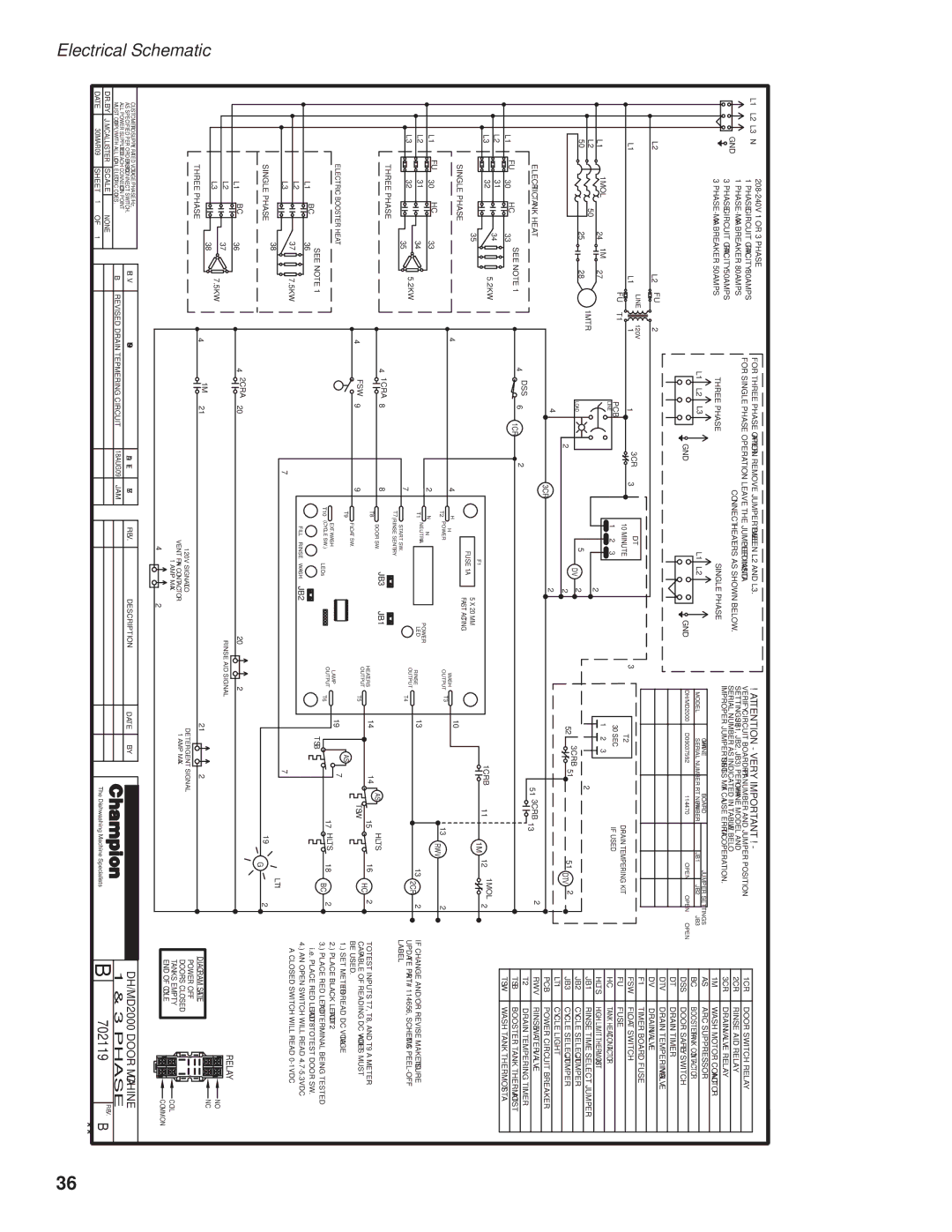
GE DH2000 operation manual Phase

DH2000 specifications

The GE DH2000 is a powerful and versatile gas turbine engine developed by General Electric, renowned for its high efficiency and reliability. As part of GE’s advanced hybrid technology lineup, the DH2000 is designed to cater to various applications, particularly in the power generation and industrial sectors.

One of the primary features of the GE DH2000 is its advanced aerodynamic design. The engine utilizes a high-efficiency compressor system, which enhances overall performance while reducing fuel consumption. This feature is essential in today’s energy-conscious world, where businesses are looking to minimize operational costs while meeting growing energy demands.

The DH2000 incorporates cutting-edge materials and manufacturing techniques, including advanced ceramic matrix composites and single-crystal superalloys. These materials provide excellent thermal resistance, allowing the engine to operate at higher temperatures, which directly contributes to improved efficiency. This design philosophy not only maximizes power output but also extends the lifespan of critical components.

In terms of technology, the GE DH2000 leverages digital solutions for monitoring and optimization. Its integrated control system allows real-time diagnostics and predictive maintenance, which are crucial for minimizing downtime and ensuring smooth operations. This digital capability enhances the engine's responsiveness and adaptability to changing load demands.

Moreover, the DH2000 features a modular design, which simplifies maintenance and repair processes. This modularity ensures shorter turnaround times during maintenance schedules, thus optimizing the overall operational efficiency of the system.

One of the standout characteristics of the GE DH2000 is its environmental performance. The engine is designed to meet stringent emissions regulations, ensuring that it produces minimal environmental impact. The incorporation of advanced combustion technologies reduces nitrogen oxides and carbon monoxide emissions, contributing to a cleaner operational footprint.

Finally, the GE DH2000’s versatility allows it to be utilized in various settings, from combined cycle power plants to industrial applications. With its robust performance, high efficiency, and flexible operation, the DH2000 is poised to meet the challenges of modern energy requirements while paving the way for a sustainable future. In conclusion, the GE DH2000 is a cutting-edge gas turbine engine that embodies innovation and efficiency, making it a preferred choice for industries seeking reliable and environmentally friendly power solutions.