|
|
|
|
|
|
|
| Rear Panel Overview |
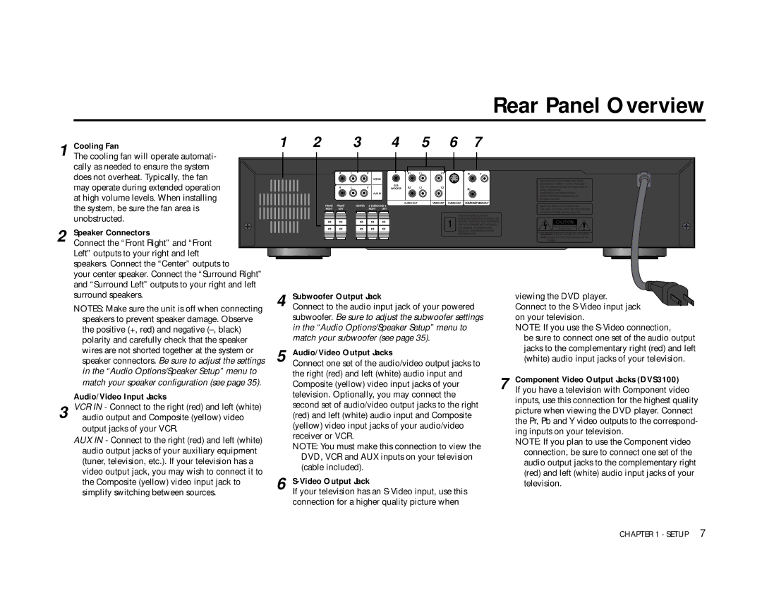
1 | Cooling Fan | 1 | 2 | 3 | 4 | 5 | 6 | 7 |
The cooling fan will operate automati- |
|
|
|
|
|
|
| |
| cally as needed to ensure the system |
|
|
|
|
|
|
|
| does not overheat. Typically, the fan |
|
|
|
|
|
|
|
| may operate during extended operation |
|
|
|
|
|
|
|
| at high volume levels. When installing |
|
|
|
|
|
|
|
| the system, be sure the fan area is |
|
|
|
|
|
|
|
| unobstructed. |
|
|
|
|
|
|
|
2 Speaker Connectors
Connect the “Front Right” and “Front Left” outputs to your right and left speakers. Connect the “Center” outputs to
your center speaker. Connect the “Surround Right” and “Surround Left” outputs to your right and left surround speakers.
NOTES: Make sure the unit is off when connecting speakers to prevent speaker damage. Observe the positive (+, red) and negative
Audio/Video Input Jacks
3 VCR IN - Connect to the right (red) and left (white) audio output and Composite (yellow) video output jacks of your VCR.
AUX IN - Connect to the right (red) and left (white) audio output jacks of your auxiliary equipment (tuner, television, etc.). If your television has a video output jack, you may wish to connect it to the Composite (yellow) video input jack to simplify switching between sources.
4 Subwoofer Output Jack
Connect to the audio input jack of your powered subwoofer. Be sure to adjust the subwoofer settings in the “Audio Options/Speaker Setup” menu to match your subwoofer (see page 35).
5 Audio/Video Output Jacks
Connect one set of the audio/video output jacks to the right (red) and left (white) audio input and Composite (yellow) video input jacks of your television. Optionally, you may connect the second set of audio/video output jacks to the right (red) and left (white) audio input and Composite (yellow) video input jacks of your audio/video receiver or VCR.
NOTE: You must make this connection to view the DVD, VCR and AUX inputs on your television (cable included).
6 S-Video Output Jack
If your television has an
viewing the DVD player. Connect to the
on your television.
NOTE: If you use the
be sure to connect one set of the audio output jacks to the complementary right (red) and left (white) audio input jacks of your television.
7 Component Video Output Jacks (DVS3100)
If you have a television with Component video inputs, use this connection for the highest quality picture when viewing the DVD player. Connect the Pr, Pb and Y video outputs to the correspond- ing inputs on your television.
NOTE: If you plan to use the Component video connection, be sure to connect one set of the audio output jacks to the complementary right (red) and left (white) audio input jacks of your television.
CHAPTER 1 - SETUP 7
